Rockwell Automation 1413-ME-PEA Capacitor Bank Controller - Series B User Manual
Page 14
Publication 1413-UM001C-EN-P - May 2006
12 Installation
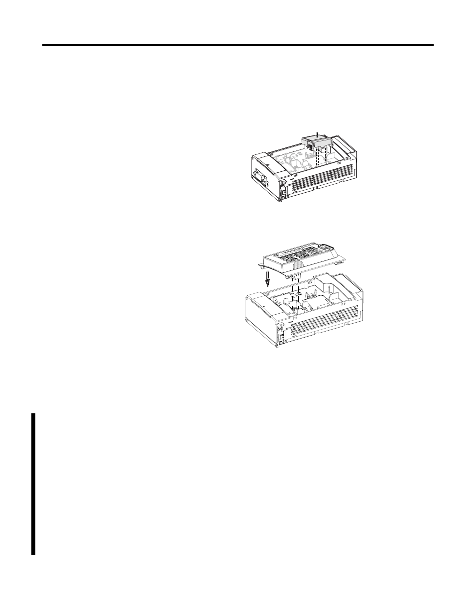
3. Install the MicroLogix memory module (7a).
This module may be found packaged with the Powermonitor
meter (7).
4. Install the data access terminal (3).
5. Connect the MicroLogix 1500 controller to 120V ac control
power, earth ground, capacitor step contactors (or interposing
relays as required), and an alarm circuit as shown in the wiring
diagram.
Wire the Controller
Fault-protection relays can be used to immediately discharge all or
specific capacitor steps during a fault occurrence. Input 0 is wired to a
normally closed fault-protection relay and discharges all capacitor
steps during a fault occurrence (low-state condition). Inputs 1… 10
are wired to normally closed fault-protection relays, and discharges its
respective capacitor step during a fault occurrence (low-state
condition). If fault protection is not being used for a specific capacitor
step, then that respective input is wired closed using the controller
supplied 24V dc power.
A normally-open momentary pushbutton is wired to Input 11. This
pushbutton is used to reset the controller after a fault occurrence.