Controller wiring diagram – Rockwell Automation 1413-ME-PEA Capacitor Bank Controller - Series B User Manual
Page 15
Publication 1413-UM001C-EN-P - May 2006
Installation 13
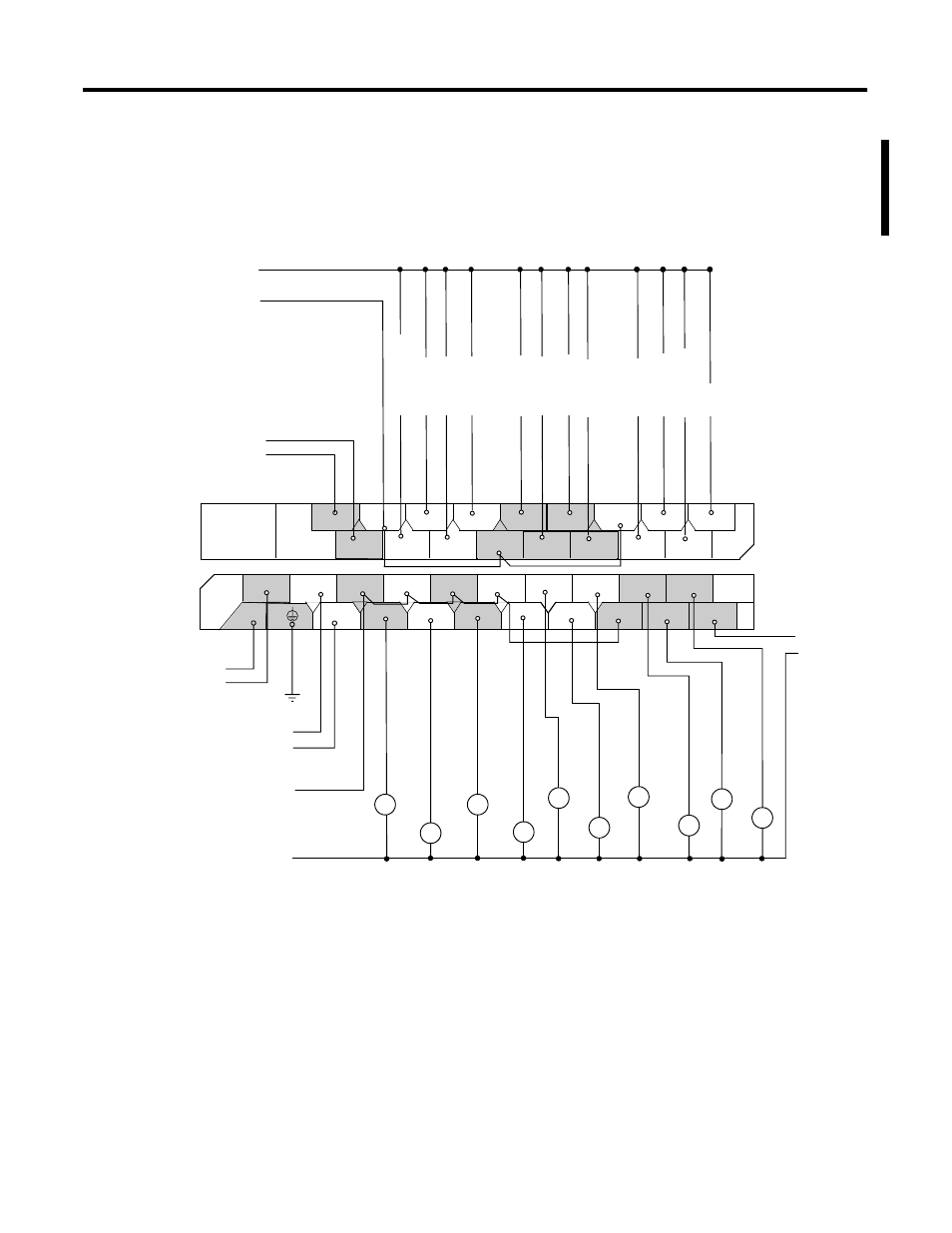
Output 0 is used as an alarm relay and is wired normally open to an
external alarm indicator. Output 1…10 is wired to normally-open
contactors for each respective capacitor step.
Controller Wiring Diagram
1764-24BWA
Ground
2
4
3
5
6
7
8
9
10
Capacitor Step Contractors or Interposing Relays
Capacitor Step Contractors or Interposing Relays
Fault Relay 1
Fault Relay 2
Fault Relay 3
Fault Relay 4
Fault Relay 5
Fault Relay 6
Fault Relay 7
Fault Relay 8
Fault Relay 9
Fault Relay 10
Reset
1
Spare Output
24V dc
to AIC+
120V ac
Control
Power
Fault Relay Power
I / 1
I / 0
I / 3
I / 2
I / 4
DC
COM 1
I / 6
I / 5
DC
COM 2
I / 7
I / 9
I / 8
I / 11
I / 10
DC
POWER
OUT
24BWA
COM
VAC
VDC 0
85-265
VAC
O / 5
VAC
VDC 1
VAC
VDC 2
VAC
VDC 4
O / 7
O / 8
O / 10
O / 4
O / 1
O / 0
O / 2
O / 6
O / 9
O / 11
VAC
VDC 5
24BWA
VAC
VDC 3
O / 3
L2
L1
COM 0
DC
Master Fault Relay
Group 0
Group 2
Group 1
Group 1
Group 2
Group 3
Group 4
Group 5
Inputs
Outputs
Isolated Alarm Output
Capacitor Step
Control Power