Aic + interface converter (all configurations), Powermonitor meter (all configurations) – Rockwell Automation 1413-ME-PEA Capacitor Bank Controller - Series B User Manual
Page 16
Publication 1413-UM001C-EN-P - May 2006
14 Installation
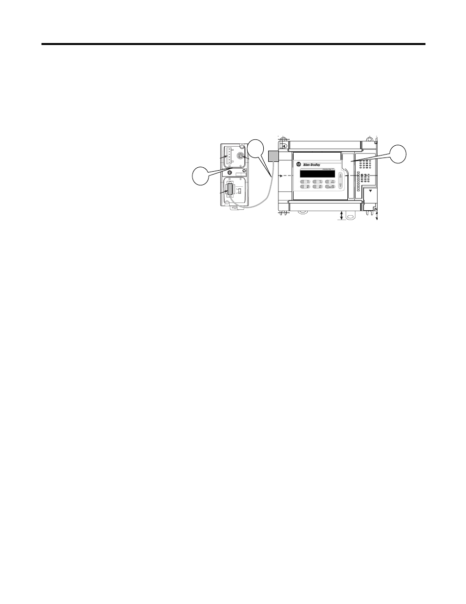
AIC + Interface Converter (All Configurations)
1. Mount the AIC+ communications converter (4) within 45 cm
(18 in.) of the left edge of the MicroLogix 1500 controller.
2. Connect the DB9 to DB9 cable (5) between Port 1 of the AIC+
(4) and Channel 1 of the MicroLogix 1500 controller (1).
3. Connect a source of 24V dc to the control power terminals on
the bottom of the AIC+.
The 24V dc power may be obtained from the DC Power Out
terminals on the MicroLogix 1500 controller.
4. Verify that the DC Source switch is in the External position and
that the Baud Rate selector is set to ‘Auto’.
Powermonitor Meter (All Configurations)
1. Mount the Powermonitor meter (7) within 1200 m (4000 ft) of
the AIC+ communications converter (4).
2. Use a 2-conductor shielded cable, that you provide, to connect
the AIC+ RS-485 port to the Powermonitor RS-485 port.
1
4
5