Control wiring – Rockwell Automation 160 AC DRIVE SER B/FRN 5-6.XX User Manual
Page 20
Chapter 2 – Installation and Wiring
2-7
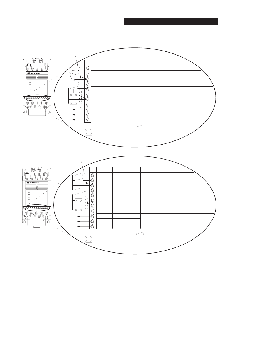
Control Wiring
8
7
6
5
4
3
2
1
9
1
10
1
+ 10V Pot
Pot Wiper or
+10/–10V DC Input
Common
4–20mA Input
Reverse
Start
Common
Stop
Normally Closed
Relay Common
Normally Open
Signal
Specification
10 k
Ω
Potentiometer, 2 Watts
Controller Input Impedance = 100 k
Ω
Controller Input Impedance = 250
Ω
Contact closure input required to operate controller
➀
Contact closure input
➀
Contact closure input
➀
Terminal
TB3
Customer-programmable relay outputs.
Resistive load 0.4A at 125V AC 2A at 30V DC.
Inductive load 0.2 A at 125V AC 1A at 30V DC.
FAULT
READY
Figure 2.3 – TB3 Control Wiring for Analog Signal Follower Model
FAULT
READY
8
7
6
5
4
3
2
1
9
1
10
1
SW1
SW2
Common
SW3
Reverse
Start
Common
Stop
Normally Closed
Relay Common
Normally Open
Signal
Specification
Contact closure input
➀
➀
Internal 12V supply.
Contact closure input
➀
Contact closure input
➀
Contact closure input required to operate controller
➀
Contact closure input
➀
Contact closure input
➀
Terminal
TB3
Customer-programmable relay outputs.
Resistive load 0.4A at 125V AC 2A at 30V DC.
Inductive load 0.2 A at 125V AC 1A at 30V DC.
Shielded Wire
Figure 2.4 – TB3 Control Wiring for Preset Speed Model
➁
Do not exceed control wiring length of 15 meters (50 feet)
.
Control signal cable length is highly dependent on
electrical environment and installation practices. To improve noise immunity the control terminal block common
must be connected to earth ground.
➂
This diagram shows “three wire” control. Refer to the following page for diagrams of other control wiring methods.
Common
➁
Common
➁
Shielded Wire
➂
➂
= N.O. Maintained Contact
= N.C. Momentary Contact
= N.O. Momentary Contact
Common
➁
= N.O. Maintained Contact
= N.C. Momentary Contact
= N.O. Momentary Contact
Common
➁