Chapter 2, Installation and wiring, Installation and storage – Rockwell Automation 160 AC DRIVE SER B/FRN 5-6.XX User Manual
Page 14: Ce compliance, Mounting requirements, Controller features
Chapter 2
Installation and Wiring
2-1
Installation and Storage
Take these actions to prolong controller life and
performance:
D store within an ambient temperature range of
–40
_ to +85_C
D store within a relative humidity range of 0%
to 95%, non-condensing
D protect the cooling fan by avoiding dust or
metallic particles
D avoid storing or operating the controller where
it could be exposed to a corrosive atmosphere
D protect from moisture and direct sunlight
D operate at an ambient temperature range of 0_
to +50
_C
To maintain proper working conditions, install the
controller on a flat, vertical and level surface. Use
mounting screws up to 4.5mm (0.177 inches) in
diameter or mount on 35mm DIN Rail.
CE Compliance
Refer to Appendix B for detailed information.
Mounting Requirements
Description
Metric
English
Min. Panel Thickness (14 GA)
1.9mm
0.0747 in.
Mounting Base Screws
m4 x 0.7
# 8–32
Mounting Torque
1.13 to 1.56 Nm. 10–14 lb. in.
D See Appendix A for details on controller
dimensions and weights.
D There must be a minimum of 12.5mm
(0.5 inches) clearance around all sides of the
controller. Use either DIN rail or mounting
holes. (Use the drilling template at the back of
the manual for mounting the controller.)
D Leave debris cover attached during controller
installation to protect from falling debris. To
ensure proper controller operation, remove
cover before applying power.
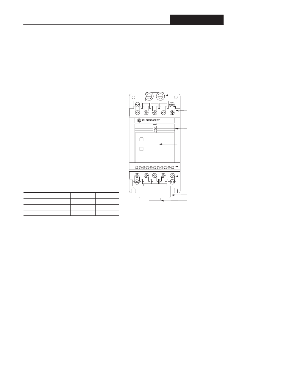
Controller Features
Figure 2.1 below details the features of both the
Analog Signal Follower and Preset Speed models.
Important: The features are the same for single
and three phase units.
Figure 2.1 – Controller Features
Ground Tab/
Protective Earth
Terminal Block One
(TB1) – For Line
Power. ➀
Terminal Block Three
(TB3) – For Control
Wiring.
Terminal Block Two
(TB2) – For Motor
Wiring. ➀
Ready/Fault
Indicating Panel –
Standard for Bulletin
160 controllers. ➃
Fan
LEDs – Indicate
operational status.
FAULT ➁
8
7
6
5
4
3
2
1
9
1
10 1
READY ➂
S
T
–
L3
L2
L1
BR
+
R
T1
T2
T3
+
V
DC
DC
–
U
W
DIN Latch
BR
➀
Refer to Figure 2.2
➁
The FAULT (red) indicator illuminates when a controller fault
condition exists. Refer to Chapter 6 for details on how to clear a fault
and general troubleshooting procedures.
➂
The READY (green) indicator illuminates when the DC bus is
charged and the controller is ready to run.
➃
Bulletin 160 controllers are fully functional when installed with a
Ready/Fault indicating panel. All control functions can be performed
from the control terminal block (TB3). Factory default parameter
settings cannot be changed with the Ready/Fault indicating panel.
A Program Keypad Module can be ordered separately, Catalog
160-P1, or as a factory-installed option by adding “P1” to the end of
the catalog number. Refer to Chapter 3, Program Keypad Module
for a detailed explanation of functionality.