MTS Acumen User Manual
Page 160
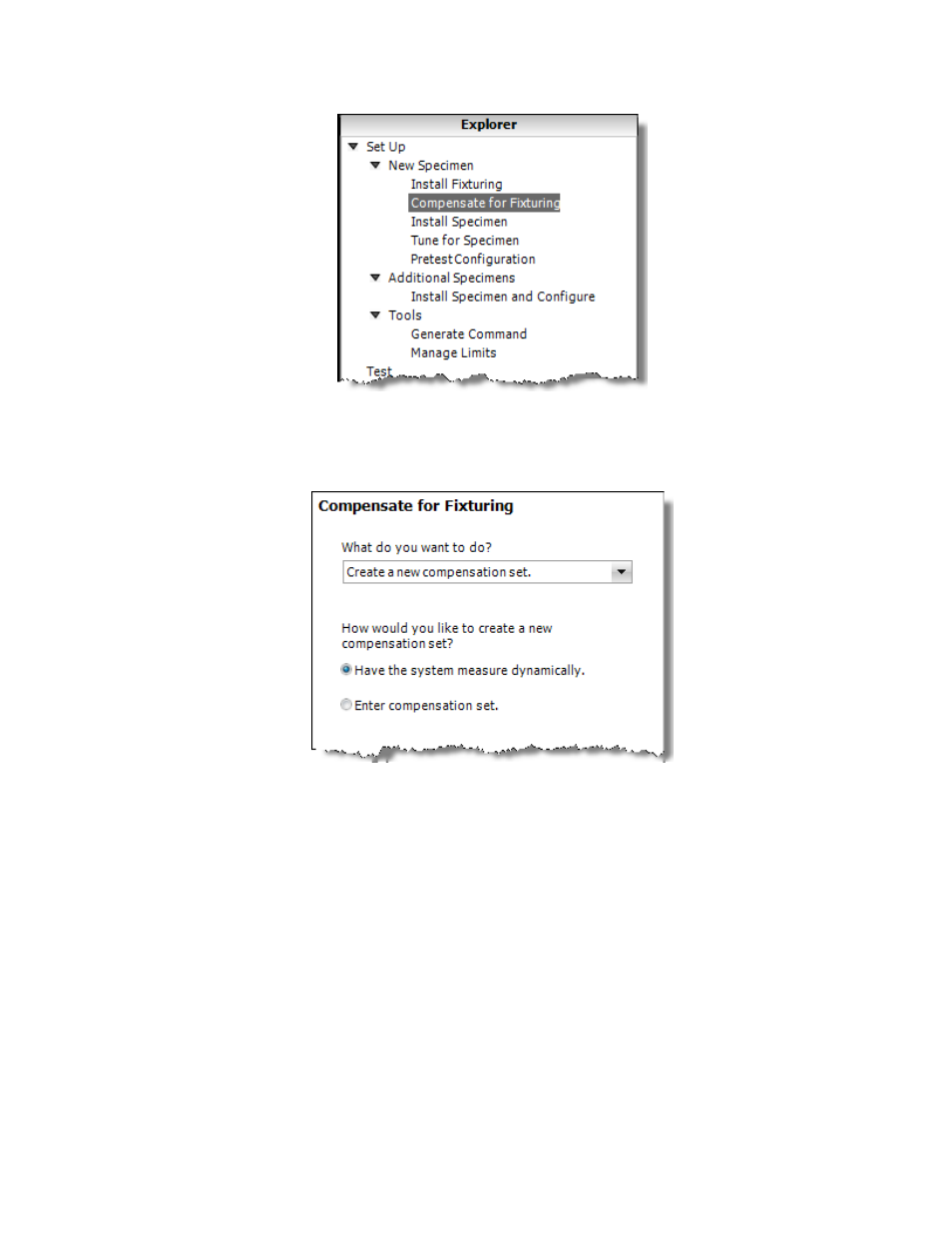
Explorer Tab
2. In the Compensate for Fixturing panel, select Create a new compensation set in the drop-down menu
for What do you want to do?, and click the Have the system measure dynamically radio button.
Compensate for Fixturing Panel
3. Click Next.
4. Below Define Command, enter the values to create a modeling program that will generate load feedback
from which the application will model compensation values. The modeling program will always run in
Stable Displacement control mode.
5. Prepare the system to run the verification program. This may involve applying power, clearing interlocks,
and so on. The system is ready when you see a green check mark in the box with the text System is
ready to compensate.
6. Click the green arrow run button to apply the modeling program. Click the Scope tab and observe the
results (load feedback in response to the command). While the modeling program is running, the
waveforms you see will depend on the characteristics your specimen and fixturing.
7. When the modeling program is complete, the Acceleration Compensation Quality graph shows results.
The best results are when the indicator is in the green area on the far right of the graph.
8. If you are satisfied with your results, click Done. If you are not satisfied with the results, click Adjust
and continue with the next step.
160 | MTS Acumen
™
Best Practices for Other System Configurations and Tests