Lenze TCF Series User Manual
Page 56
P51
SOFTWARE VERSION
This displays the software version number for the control board software . This information is
useful when contacting the factory for programming or troubleshooting assistance .
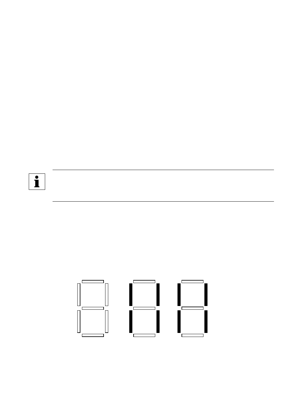
The software version is displayed in two parts which alternate . The first part is the software
version, and the second part is the revision number . For example, if the display shows "106"
and "-02" this indicates that the drive contains the second revision of version 106 software .
P52
DC BUS VOLTAGE
This displays the DC bus voltage in percent of nominal . Nominal DC bus voltage is determined
by multiplying the drive’s nameplate input voltage rating by 1 .4 .
P53
MOTOR VOLTAGE
This displays the output voltage in percent of the drive’s nameplate output voltage rating .
P54
MOTOR LOAD
This displays the motor load in percent of the drive’s output current rating .
P55
0-10 VDC ANALOG INPUT
This displays the level of the 0-10 VDC analog input signal at TB-5 . A reading of 100%
indicates a 10 VDC input at TB-5 .
NOTE
If the -10 to +10 VDC bipolar input is used, this parameter will display 0% at -10
VDC, 50% at 0 VDC, and 100% at +10 VDC .
P56
4-20 mA ANALOG INPUT
This displays the level of the 4-20 mA analog input signal at TB-25 . A reading of 20% indicates
a 4 mA input at TB-25, and a reading of 100% indicates a 20 mA input at TB-25 .
P57
TERMINAL STRIP STATUS
This indicates the status of several terminals using the vertical segments of the LED display .
An illuminated segment indicates that the particular terminal is closed with respect to TB-
2 . The CHARGE RELAY is not a terminal, and should always be illuminated . Refer to the
diagram herein .
CHARGE
RELAY
TB-1
TB-13D
TB-13A
TB-13B
TB-15
TB-14
TB-13C
52