Lenze TCF Series User Manual
Page 23
10 .7
ANALOG OUTPUT SIGNALS
Terminal TB-30 can provide a 0-10 VDC or a 2-10 VDC signal proportional to output
frequency, load, or torque . The 2-10 VDC signal can be converted to a 4-20 mA signal using
a resistor in series with the signal such that the total load resistance is 500 Ohms . Refer to
TB-30 OUTPUT (Parameter 08) in Section 15 - DESCRIPTION OF PARAMETERS .
10 .8
DRIVE STATUS DIGITAL OUTPUTS
There are two open-collector outputs at terminals TB-14 and TB-15 . The open-collector
circuits are current-sinking types rated at 30 VDC and 50 mA maximum .
The open-collector outputs can be programmed to indicate any of the following: RUN,
FAULT, INVERSE FAULT, FAULT LOCKOUT, AT SPEED, ABOVE PRESET SPEED #3,
CURRENT LIMIT, AUTO SPEED MODE, and REVERSE . Refer to Parameters 06 and 13 in
Section 15 - DESCRIPTION OF PARAMETERS .
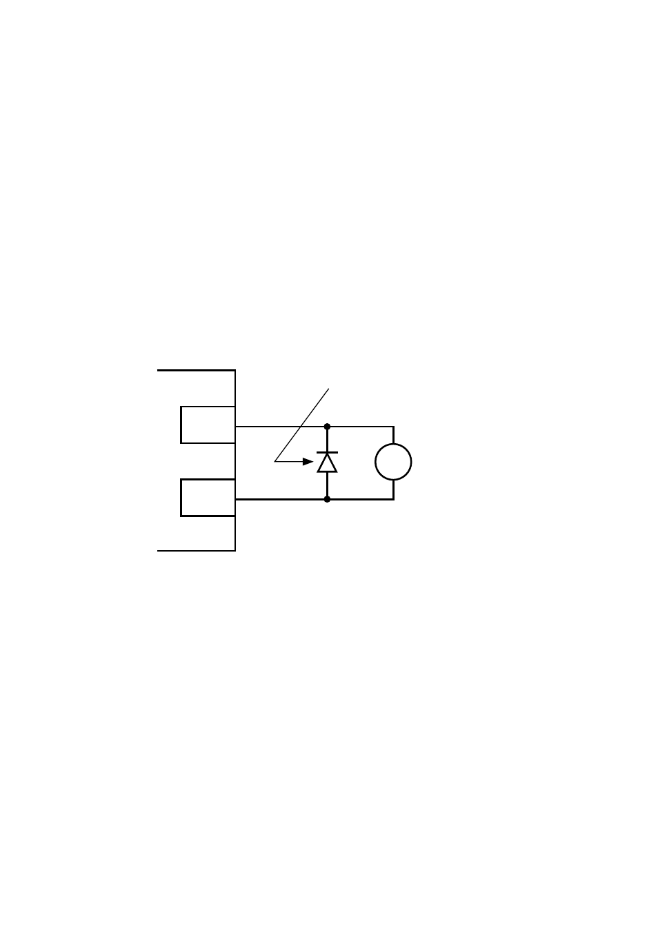
The following diagram illustrates how the 12 VDC power supply at TB-11 can be used with
the open- collector output to drive an external relay .
TB-11
TB-14
TCF
TERMINAL
STRIP
RELAY COIL
DIODE SNUBBER
(1N4148 or Equivalent)
19