11 tcf control wiring diagrams – Lenze TCF Series User Manual
Page 24
11
TCF CONTROL WIRING DIAGRAMS
11 .1
TCF TERMINAL STRIP
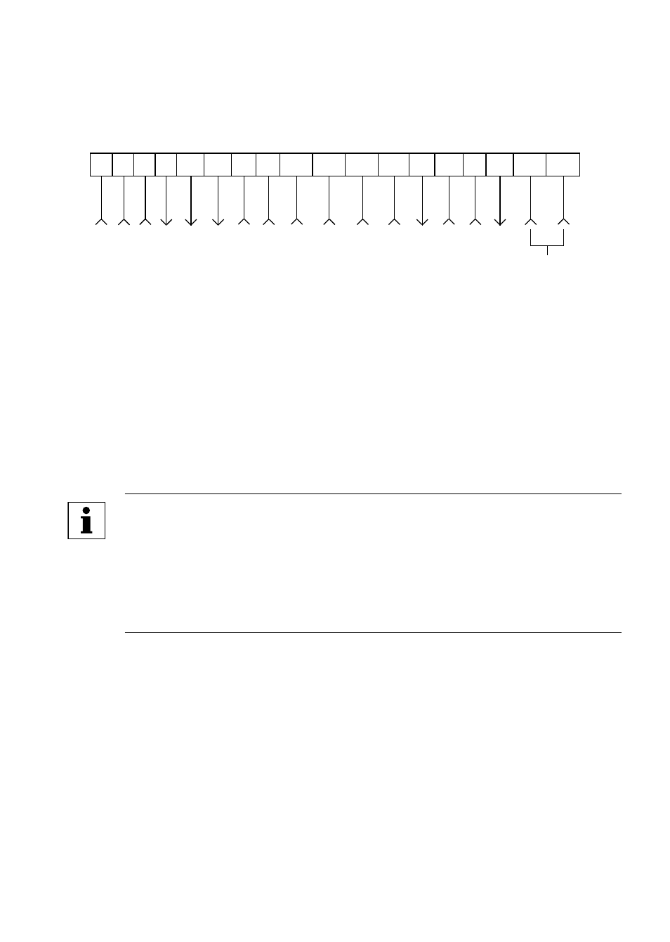
The following diagram represents the terminal strip on the main control board and provides a
brief description of the function of each terminal .
ANALOG
SIGNAL
COMMON
0-10
VDC
SPEED
REFERENCE
INPUT
10
VDC
SUPPLY
FOR
SPEED
POT
0-10
OR
2-10
VDC
OUTPUT
DIGITAL
INPUT
REFERENCE
RUN
TB-13A
FUNCTION
SELECT
TB-13B
FUNCTION
SELECT
TB-13C
FUNCTION
SELECT
OPEN-COLLECTOR
OUTPUT
OPEN-COLLECTOR
OUTPUT
RS-485
SERIAL
COMMUNICATIONS
4-20
mA
SPEED
REFERENCE
INPUT
12
VDC
SUPPLY
(50
mA
MAX)
1 2 5 6
14
TXA TXB
4
13A 13B
13C
4
13D
25
11
15
30
2
TB-13D
FUNCTION
SELECT
ANALOG
SIGNAL
COMMON
DIGITAL
INPUT
REFERENCE
NOTE
• The function of terminals TB-13A, TB-13B, TB-13C, TB-13D, TB-14, TB-
15, and TB-30 are dependent on the programming of certain parameters .
Refer to Section 15 - DESCRIPTION OF PARAMETERS .
• The following diagrams and their corresponding notes assume that all of
the parameters, other than those required for the particular configuration,
remain at factory default settings .
Additional information on operating the drive from the terminal strip can be found in Section
10 . The diagrams in sections 11 .2 - 11 .6 provide a quick reference on wiring the drive for the
most common configurations using dry contacts to activate the digital inputs . If solid-state
circuits are to be used, refer to APPENDIX B - INPUT ASSERTION LEVEL, as the assertion
level of the digital inputs may have to be changed to active-low .
20