9tcf power wiring diagram – Lenze TCF Series User Manual
Page 19
9
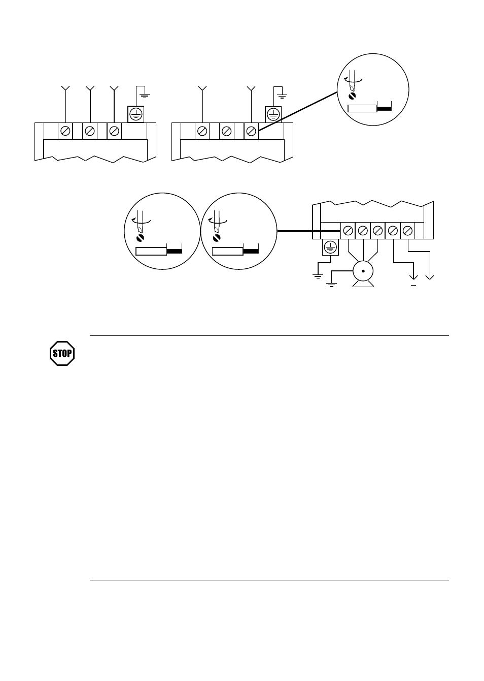
TCF POWER WIRING DIAGRAM
THREE PHASE INPUT
(ALL SERIES)
L1
L2
L3
OUTPUT (ALL SERIES)
3 PHASE
AC MOTOR
DC BUS
VOLTAGE
T1 T2 T3 B- B+
+
SINGLE PHASE INPUT
(TF200Y SERIES)
L1
L2
L3
For all other models,
use output torque values .
TF230Y &
TF250 only
7 .0 lb-in / 0 .8 Nm
0 .24 in / 6 mm
0 .5 - 5 HP
(0 .37 - 3 .7 kW)
4 .5 lb-in / 0 .5 Nm
0 .24 in / 6 mm
7 .5 - 10 HP
(5 .5 - 7 .5 kW)
10 lb-in / 1 .2 Nm
0 .35 in / 9 mm
STOP!
•
Do NOT connect AC line power to output terminals T1, T2, or T3 . Severe
damage to the drive will result .
•
Leakage current may exceed 3 .5 mA AC . Minimum size of the protective
earth conductor shall comply with local safety regulations for high leakage
current equipment .
•
Wire and Ground in accordance with NEC or CEC, and all applicable
local codes .
•
Motor wires MUST be run in a separate steel conduit away from control
wiring and incoming AC power wiring .
•
Do not install contactors between the drive and the motor without
consulting Lenze-AC Tech for more information . Failure to do so may
result in drive damage .
•
Use only UL and CSA listed and approved wire .
•
Minimum wire voltage rating is 300 V for 120, 208, and 240 Vac systems,
and 600 V for 400 and 480 Vac systems .
•
Wire gauge must be based on a minimum of 125% of the rated input/
output current of the drive, and a minimum 75°C insulation rating . Use
copper wire only .
15