Lenze TCF Series User Manual
Page 29
11 .6
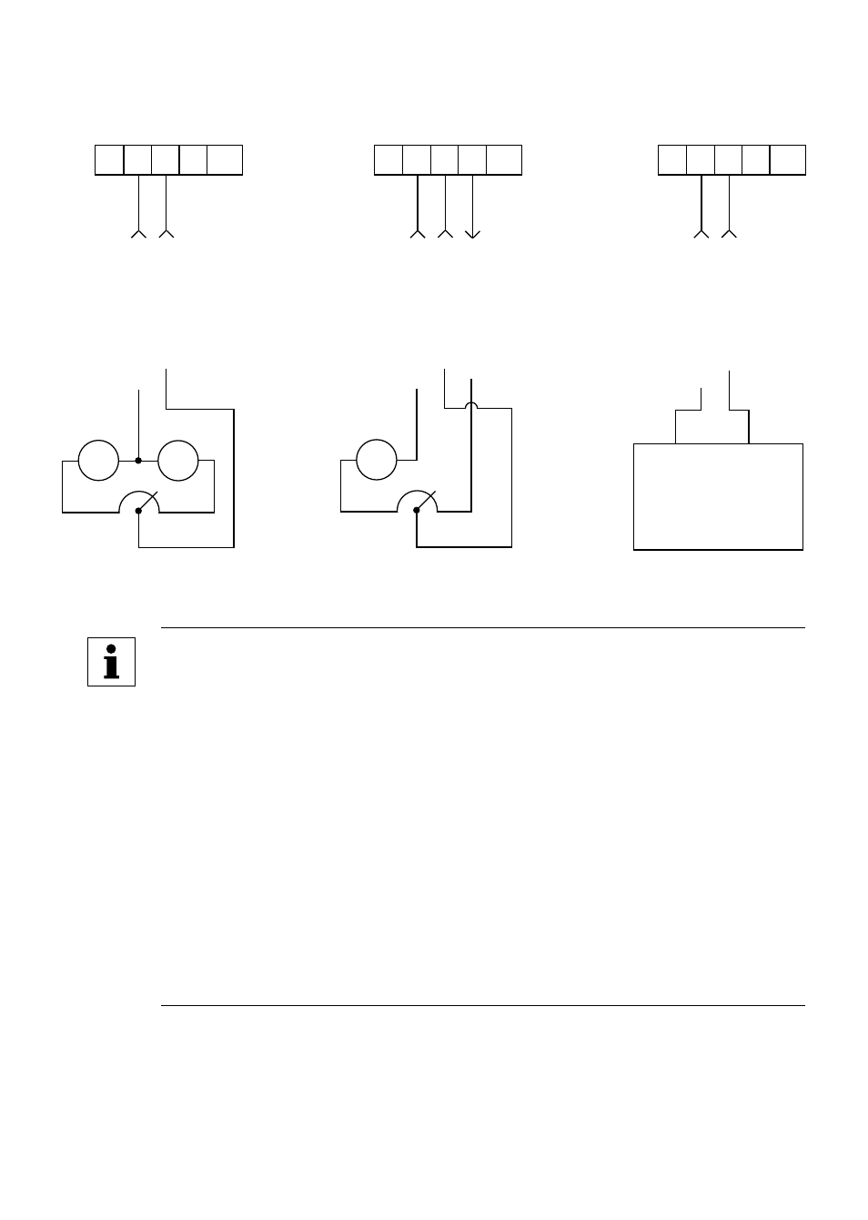
BIPOLAR SPEED CONTRO L (-10 to +10 VDC)
The three wiring diagrams herein provide examples of using a -10 to +10 VDC bipolar speed
reference .
SIGNAL
COMMON
0-10
VDC
INPUT
1 2 5 6 11
-10 to +10 VDC
SOURCE
(such as PLC)
SIGNAL
COMMON
0-10
VDC
INPUT
1 2 5 6 11
10V
10V
SPEED POT
(2 .5k - 10 kΩ)
-
+ -
+
SIGNAL
COMMON
0-10
VDC
INPUT
1 2 5 6 11
+10
VDC
SUPPLY
10V
SPEED POT
(2 .5k - 10 kΩ)
-
+
(COM) (SIGNAL)
NOTES:
• To use a -10 to +10 VDC speed reference signal, the following parameters
must be set:
P07 BIPOLAR REFERENCE SELECTION must be set to ENABLE (02) .
P17 ROTATION must be set to FORWARD AND REVERSE (02) .
P45 SPEED AT MIN SIGNAL must be set to the maximum desired
speed in the reverse direction .
P46 SPEED AT MAX SIGNAL must be set to the maximum desired
speed in the forward direction .
• In this configuration, all other speed references are disabled except JOG
FORWARD and JOG REVERSE .
• In this configuration, the RUN and START functions on TB-13A and
TB-13D will only start the drive, they will not select direction . Direction is
determined by the polarity of the -10 to +10 VDC signal .
25