15 description of parameters – Lenze TCF Series User Manual
Page 40
15
DESCRIPTION OF PARAMETERS
P01
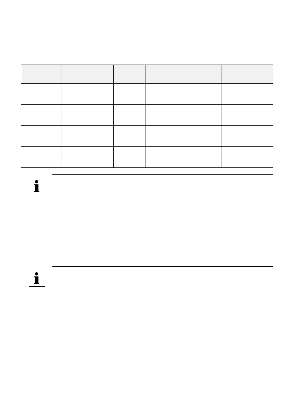
LINE VOLTAGE SELECTION
This calibrates the drive for the actual applied input voltage, and can be set to HIGH (01) or
LOW (02) . Refer to the table below for the proper setting depending on the input voltage .
MODEL
RATED INPUT
VOLTAGE
INPUT
PHASE
APPLIED INPUT
VOLTAGE
PARAMETER
SETTING
TF200Y
208 / 240 Vac
1 or 3
220 - 240 Vac
HIGH (01)
1 or 3
200 - 208 Vac
LOW (02)
TF200
208 / 240 Vac
3
220 - 240 Vac
HIGH (01)
3
200 - 208 Vac
LOW (02)
TF400
400 / 480 Vac
3
440 - 480 Vac
HIGH (01)
3
380 - 415 Vac
LOW (02)
TF500
480 / 590 Vac
3
575 - 600 Vac
HIGH (01)
3
460 - 480 Vac
LOW (02)
NOTE
If this parameter is changed while the drive is running, the new value will not
take effect until the drive is stopped .
P02
CARRIER FREQUENCY
This sets the switching rate of the output IGBT’s . Increasing the carrier frequency will result
in less audible motor noise . Available settings are: 2 kHz, 4 kHz, and 8 kHz .
The TCF drive is fully rated up to 4 kHz carrier frequency . If the 8 kHz carrier frequency is
selected, the drive’s ambient temperature rating must be de-rated to 43°C, OR the output
current rating must be de-rated to 92% .
NOTE
• If the drive's heatsink temperature gets too hot while running, the carrier
frequency will automatically shift to a lower value to increase efficiency
and lower heat generation .
• If this parameter is changed while the drive is running, the change will not
take effect until the drive is stopped .
36