11 .4 three-wire start/stop control – Lenze TCF Series User Manual
Page 27
11 .4
THREE-WIRE START/STOP CONTROL
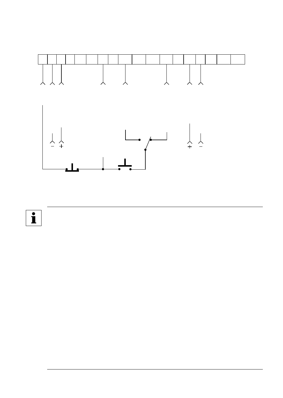
This wiring diagram shows a typical three-wire start/stop control scheme, using momentary
contacts (such as push-buttons) for START and STOP commands, and a selector switch to
select rotation direction .
MOMENTARY
STOP CONTACT
SIGNAL
COMMON
0-10
VDC
INPUT
DIGITAL
INPUT
REFERENCE
START
4-20
mA
INPUT
1
2
5 6
14
TXA TXB
4
13A 13B 13C
4
13D
25
11
15
30
2
SIGNAL
COMMON
(See Note 3)
START
FORWARD
MOMENTARY
START CONTACT
(See Note 3)
FWD
REV
START
REVERSE
NOTES
• Momentarily close TB-13A or TB-13D to TB-4 to START the drive in the
desired direction and momentarily open TB-1 to TB-4 to STOP the drive .
• For this configuration, ROTATION DIRECTION (Parameter 17) must be
set to FORWARD AND REVERSE (02), TB-13A (Parameter 10) must be
set to START REVERSE (07), and TB-13D (Parameter 49) must be set to
START FORWARD (05) .
If reverse direction is not required, wire the START push-button
directly between TB-4 and TB-13D, and do not program TB-13A for
START REVERSE.
• For 0-10 VDC or 4-20 mA speed control, use one of the following methods:
-
Program Parameter 05 - STANDARD REFERENCE SOURCE for
0-10 VDC (03) or 4-20 mA (04) . This method is preferable if only one
speed source is required, as this method leaves the TB-13 terminals
free to be used for other functions .
-
Program one of the TB-13 terminals (13B or 13C are available in
this example) for 0-10 VDC (02) or 4-20 mA (03) . When that TB-13
terminal is closed to TB-4, the drive will respond to the selected
speed reference signal . If that TB-13 terminal is not closed to TB-
4, the drive will respond to the speed control source selected in
Parameter 05 - STANDARD REFERENCE SOURCE .
23