Coil tine harrow installation, Figure 3-32: coil tine arm spring adjustment – Landoll 2131 Wing Coulter Chisel User Manual
Page 74
3-38
F-721-0513 Edition
ASSEMBLY INSTRUCTIONS
Coil Tine Harrow Installation
See Figures 2-20 thru 2-22 for 3 Row Coil Tine Harrow
placement dimensions.
1.
Install 2 hole support plate into coil tine harrow arm
assembly. Use (2) 3/4-10 x 3 hex head cap screws to
hold plate in place.
2.
Slide coil tine harrow arm assemblies over rear frame
bar using chopper reel placement drawings (See
Figures 2-20 thru 2-22 and 3-31.)
3.
Attach top plate to top of chopper reel arm assembly
using (4) 3/4-10 x 13 hex head cap screws. Slide arm
support tube and bottom plate onto 13” hex head cap
screws on underside of chopper reel arm assembly
and rear frame (See Figure 3-31.)
4.
Evenly tighten the 3/4-10 x 13 hex head cap screws
first. Then tighten the front 3/4-10 x 2 hex head cap
screw. Tighten 3/4-10 x 3 hex head cap screws last,
but be sure to not overtighten. These screws need to
be snug.
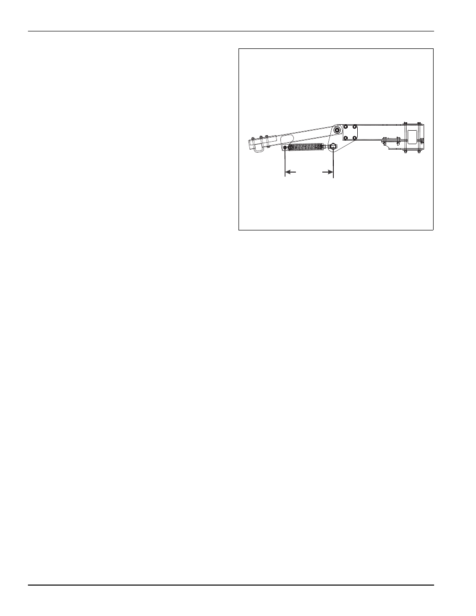
5.
Adjust spring to 21-1/2” (See Figure 3-32.)
6.
Attach harrow arms to 3 row coil tine harrow
assembly using u-bolts, and 5/8-11 flange head
serrated nuts. The u-bolt will go through both the
harrow arm and harrow stiffener plate.
Figure 3-32: Coil Tine Arm Spring Adjustment
21-1/2”
2130-21-tine-2