Hydraulic installation – Landoll 2131 Wing Coulter Chisel User Manual
Page 56
3-20
F-721-0513 Edition
ASSEMBLY INSTRUCTIONS
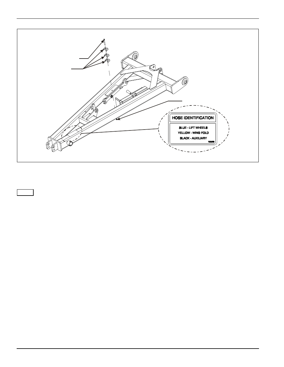
Figure 3-12: Hitch Hose Clamps and Color Designation
Hydraulic Installation
NOTE
See Figures 3-13 thru 3-18 for coulter lift, wheel lift, and
fold hydraulic diagrams.
1.
On all models, install the 16 port manifold to the
manifold bracket on the front center frame tube using
1/2-13 x 3-1/2 hex head cap screws and hex lock
nuts (See Figure 3-11.)
2.
On all models, install 8 port manifold to the manifold
bracket on the center frame weldment near the right
side of the rear fold anchor using 1/2-13 x 3-1/2 hex
head cap screws and hex lock nuts (See
Figure 3-11.)
3.
On 2131-21, 2131-23, and 2131-25 models, install
second 8 port manifold to the manifold bracket on the
center frame weldment near the right side of the front
fold anchor using 1/2-13 x 3-1/2 hex head cap
screws and hex lock nuts (See Figure 3-11.)
4.
Install 90
o
adapter in port N in the rear of the
manifold.
5.
Install straight adapters in any manifold port that has
a hose connection.
6.
Verify that limit valve is installed below the depth stop
bracket welded to the frame. If not, refer to “Depth
Stop Tube Assembly” on page 3-6.
7.
Install coulter lift, wheel lift, and fold system hoses
(See Figures 3-13 thru 3-18.)
8.
Hold each system of hoses in place using 3/8-16 x 4
hex head cap screw, hose clamps, and hex lock nut
(See Figure 3-12.)
9.
Install plugs in any remaining open manifold or valve
ports.
10. Install hose wraps around system hoses per hose
identification decal near hose couplers, putting both
hoses inside wrap(See Figure 3-12.)
3/8-16 X 4 HEX
HEAD CAP SCREW
HOSE CLAMPS
3/8-16 HEX LOCK NUT
2130 hitch hose clamps