Figure 4b – Landoll HSB 71-1 through 131-1 SOIL BUILDER Coulter Chisel - Extended Frame User Manual
Page 23
1K705
Page 21
COUL
TERS & COULTER CONTROL
A. -HYDRAULIC COULTER CONTROL
A few notes before you begin:
•Use the cast bearings (in box #7J424, 7 & 9 shank;
7J424 and 7J425, 11 & 13 shank) and the
hardware (in box #7J668, 7 & 9 shank; 7J668 &
7J860, 11 & 13 shank) to mount spring rockshaft
on top of the machine.
•Note that the 1/4 x 2 x 8” straps (four on 7 & 9
shank, seven on 11 & 13 shank) go under the
cast bearings to act as spacers. The long
studs go through these bearings as well as the
bearings for the coulter gangs.
•On 9- & 13-shank machines, attach the outer cast
bearings to the coulter support extensions bolted
to the frame.
791rev5-30-05
on the right. Nuts on the gang bolts should be
pointing outward of the machine.
•On 11 shank machines, the “9 blade”
gang goes in the center of the
machine and the “7 blade”
gangs in the outer positions.
•On 13 shank units all three gangs have nine blades.
•For 11- & 13-shank machines, one set of cast
bearings nearest the center of the machine are
held in place with 5/8-11 NC x 12” capscrews,
lock washers and nuts.
•On 7 shank machines the “8 blade” gang goes on
the left side of the machine and the “7 blade”
gangs on the right sde.
•On 9 shank units a “10 blade” gang goes on the left
side of the machine and a “9-blade” gang goes
IMPORTANT!
Coat all bearing surfaces with
grease before installing.
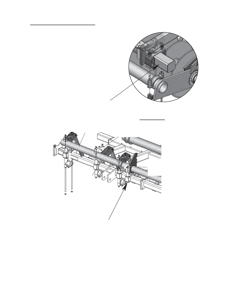
Spring Rockshaft
Cast Bearings
Strap
Spacer
Figure 4b
Cast Bearing
HHCS, 5/8-11 x 12”
Lock washer, 5/8”
Nut, 5/8-11 NC
Figure 4a