Frame assembly – Kinze 3500 Lift and Rotate Planter Rev. 5/14 User Manual
Page 75
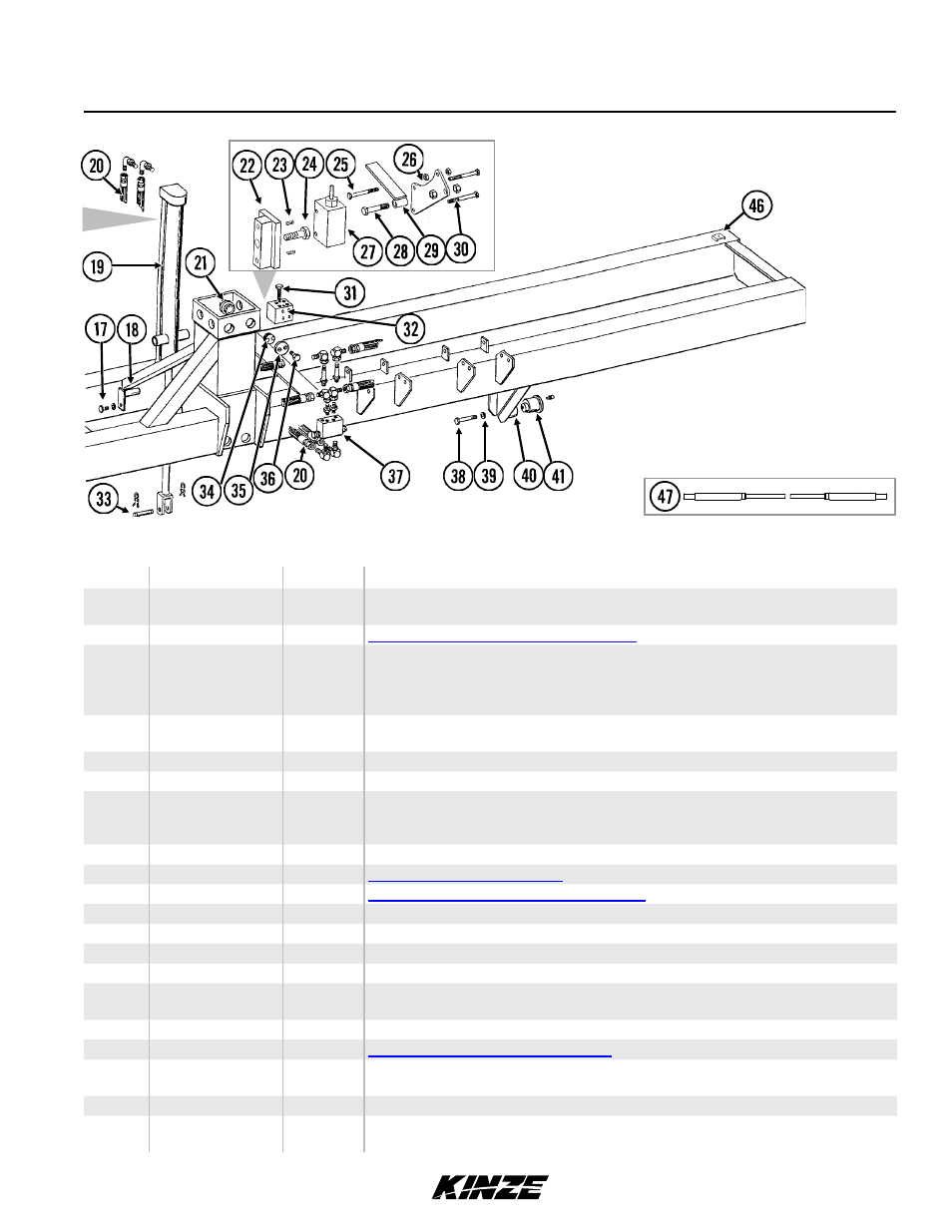
Frame Assembly
ITEM
PART NO.
QTY.
DESCRIPTION
11
G10004
G11091
2
2
Hex Head Cap Screw, ⅜"-16 x 1¼"
Serrated Flange Nut, ⅜"-16
12
---
-
See “Electrical Components” on page P101
13
G10064
G10227
G10103
G10110
-
-
-
-
Hex Head Cap Screw, ¼"-20 x 1"
Lock Washer, ¼"
Hex Nut, ¼"-20
Lock Nut, ¼"-20, Grade B
14
G10305
G11091
2-4
2-4
Carriage Bolt, ⅜"-16 x 1"
Serrated Flange Nut, ⅜"-16
15
GD15950
1
Light Mount Extension
16
GD12724
1
Bracket
17
G10037
G10228
G10102
2
2
2
Hex Head Cap Screw, ½"-13 x 1¼"
Lock Washer, ½"
Hex Nut, ½"-13
18
GA5121
2
Pin, 2⅛"
19
---
-
See “Lift Cylinder” on page P94
20
---
-
See “Planter Hydraulic System” on page P99
21
GD9093
16
Poly Wear Pad
22
GA6850
1
Valve Mount
23
G10120
2
Hex Socket Set Screw, ⅜"-16 x ½"
24
G10005
1
Hex Head Cap Screw, ⅝"-11 x 1¾"
25
G10638
G10103
1
2
Hex Head Cap Screw, ¼"-20 x 2"
Hex Nut, ¼"-20
26
GD10129
1
Mounting Bracket
27
---
-
See “Stroke Limiter Valve” on page P96
28
G10048
G10101
1
2
Hex Head Cap Screw, ⅜"-16 x 2"
Hex Nut, ⅜"-16
29
GA7153
1
Stroke Limiter Arm
30
G10403
G10227
2
2
Hex Head Cap Screw, ¼"-20 x 2½"
Lock Washer, ¼"
Model 3500
M0240-02
Rev. 1/12
P72
TM