INFICON SKY CDGxxxD (Profibus) User Manual
Page 29
tira54e1-a (2009-01) CDGxxxD.cp
29
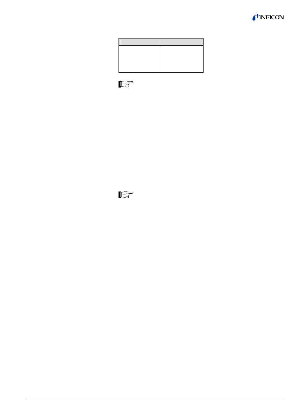
The device supports the four data units described below:
Coding (hex)
Unit
1001 COUNTS
1301 Torr
1308 mbar
1309 Pascal
For safety reasons, it is not possible to change the pressure unit while
the gauge is cyclically interchanging data with a DP/V0 master.
The data unit setting can only be modified when the gauge is in the IDLE
status.
In cyclic data traffic, the data unit must be set in the User Parameter
Data. All settings previously made in acyclic data traffic are overwritten
(
→ section "User Parameter Data").
If the data unit is set in one instance, that data unit setting applies to all
instances. Likewise, the data unit setting made in the User Parameter
Data is valid for all instances.
• This parameter indicates that the pressure reading is within a valid range. This
means that the following conditions are fulfilled:
• The gauge is in the EXECUTING status (Device Block, ID 25)
• The exception status contains no manufacturer warning or alarm
• The transducer block contains no sensor alarm (ID 103)
If this value is set to zero, the pressure reading is not valid. In such a
case, either check Exception Status (ID 26, Device Block) to find out
whether there is an error or check the Status Extension (ID 102,
Transducer Block) to find out whether the measured value is out of the
specified measuring range (overrange or underrange mode).
This parameter contains the valid maximum measurement scale of the device in
terms of the currently selected data type (ID 21) and data unit (ID 22).
This parameter determines the data type of parameter Offset-A (ID 26).
This parameter specifies an amount that is added prior to Gain to derive the
ProcessValue. This value is set after execution of the "Zero Adjust" service.
This parameter determines the value above which an Alarm Condition will occur.
The value must always lie within the boundaries specified for the Safe Value
(ID 40). See section 8.1.19.
This parameter determines the value below which an Alarm Condition will occur.
The value must always lie within the boundaries specified for the Safe Value
(ID 40). See section 8.1.19.
This parameter determines the amount by which the ProcessValue must recover to
clear an Alarm Condition. The value must always lie within the boundaries specified
for the Safe Value (ID 40). See section 8.1.19.
This parameter determines the Value above which a Warning Condition will occur.
The value must always lie within the boundaries specified for the Safe Value
(ID 40). See section 8.1.19.
8.1.7 Data Unit (ID 22)
8.1.8 Reading Valid (ID 23)
8.1.9 Full Scale (ID 24)
8.1.10 Offset-A Data Type
(ID 25)
8.1.11 Offset-A (ID 26)
8.1.12 Alarm Trip Point High
(ID 31)
8.1.13 Alarm Trip Point Low
(ID 32)
8.1.14 Alarm Hysteresis (ID 33)
8.1.15 Warning Trip Point High
(ID 35)