4 data exchange mode – INFICON SKY CDGxxxD (Profibus) User Manual
Page 12
12
tira54e1-a (2009-01) CDGxxxD.cp
4 Data Exchange Mode
The reading and writing operations defined in Profibus are based on a slot index
address scheme. In CDGxxxD, all device functions are organized in the following
blocks:
• Device
block.
Describes all organizational parameters of the gauge (serial number,
manufacturer, software version, …)
• OneOfN Analog Input Function Block.
Used to determine which function/transducer block parameter set is mapped
into the corresponding block address space.
• Sensor Analog Input Function Block.
Describes the function of the pressure presentation.
• Transducer
Block.
Describes the physical interface between the gauge and the process.
• Trip Point Function Block.
Used to model the action of the trip point relays.
• Discrete Output Function Block.
Used to control the digital outputs (Trip Function Relays).
Each block is assigned to a separate slot as shown in the table below.
Block
Slot ID
Selector = 1
Selector = 2
0 Device
Block
OneOfN Analog Input Function Block
Analog Input Function Block 1
(CDG)
Analog Input Function Block 2
(ATM)
1
CDG Transducer Block
ATM Transducer Block
2
Trip Point Function Block 1
3
Trip Point Function Block 2
4
Discrete Output Function Block 1
5
Discrete Output Function Block 2
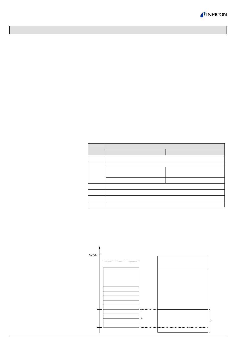
There are 254 indices per slot. The indices can have a width of 255 bytes.
All values that can be accessed via Profibus have to be mirrored to one of these
slots/indices.
The parameters are generally numbered in ascending order, starting with index 16.
Services such as "Zero Adjust" are numbered in descending order, starting with
index 15.
Index
16
0
Private
Public
Operations Public
Block_x
Parameter_2
Parameter_1
Parameter_0
Operation_1
Operation_2
Operation_n
Parameter_n
Attributes
Block_Type_Name
optional
optional
Slot x
4.1 Acyclic Data Trans-
mission with Profibus
DPV1 Functionality
Block, slot and
index assignment
Assignment of the block
elements to the slot indices