Communication card installation – Despatch Protocol Manager with Protocol 3 and Protocol Plus User Manual
Page 52
A
PPENDICES
Protocol Manager Instruction Manual
52
Version 1
Copyright © 2013 by Despatch Industries.
All rights reserved. No part of the contents of this manual may be reproduced, copied or transmitted in any form or by any
means including graphic, electronic, or mechanical methods or photocopying, recording, or information storage and
retrieval systems without the written permission of Despatch Industries, unless for purchaser's personal use.
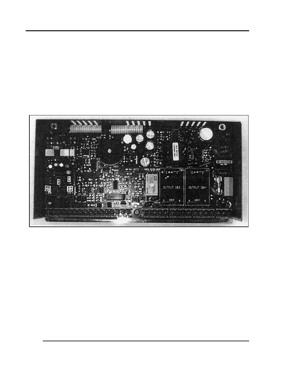
6.1.1. Communication Card Installation
1. Turn off power to the controller.
2. Remove the back cover of the controller by removing the two screws at the top of the unit.
3. Looking into the back of the controller with the connector terminal strips at the bottom:
a. Install the communication card onto the two 5 pin headers on the rear circuit board.
b. Be sure the jumper blocks on the communication card are positioned toward the bottom
of the controller.
for placement information. Be sure the card is seated firmly onto the
headers.
4. Set the jumpers on the communication card for the desired serial communication interface
5. Reinstall the back cover.
6. Wire the communication connections on the rear of the unit for the desired serial
communication interface:
RS232 Wiring Diagram (Figure 47)
RS422A Wiring Diagram (Figure 46)
RS 485 Wiring Diagram (Figure 45)
7. Reapply all power connections to the controller.
Figure 43. Controller rear view with Communications Card (left).