Controller hardware and cabling, Figure 37 – Despatch Protocol Manager with Protocol 3 and Protocol Plus User Manual
Page 45
Protocol Manager Instruction Manual
T
ROUBLESHOOTING
Version 1
45
Copyright © 2013 by Despatch Industries.
All rights reserved. No part of the contents of this manual may be reproduced, copied or transmitted in any form or by any
means including graphic, electronic, or mechanical methods or photocopying, recording, or information storage and
retrieval systems without the written permission of Despatch Industries, unless for purchaser's personal use.
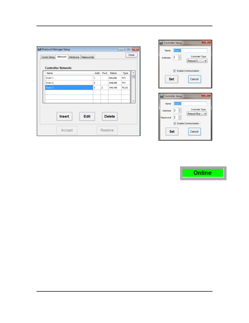
4. When the Rum Time Window green On-Line light comes on,
communication has been successfully established (Figure 38). If Online
does not light, check hardware and cabling (Section Error! Reference
ource not found.).
5.4. Controller Hardware and Cabling
5.4.1.1. Check Cabling Between Controller and Outside of Oven
In reference to Figure 39:
The T+ should be connected to terminal #19 on the back of the controller. Check using an
ohmmeter that pin #3 on the 9 pin connector connected to this terminal.
The T- should be connected to terminal #20 on the back of the controller. Check using an
ohm meter that pin #4 on the 9 pin connector connected to this terminal.
Figure 37. Check network controller parameters.
Figure 38. Run Time Window
Online light indicates
successful communication
with controllers.