Brady PAM 3000 User Manual
Page 77
C-9
Printer-Applicator-System PAM 3000
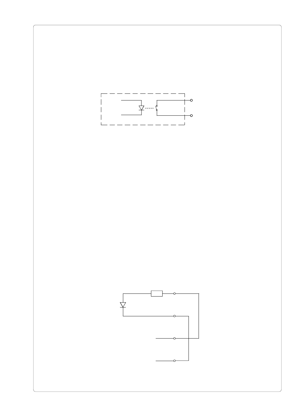
The output is recognized through solid state relays. The line is lead to the plug connector as
a RÜL signal.
The switch function of the output is to open or close the contact between the line RÜL and the
output.
Electrical requirements : U
max
= 42V
I
max
= 100mA
Fig. C-12 Circuit of the ouput
PIN3 - XSCA
PIN8 - XSCAR
Explanation of the Signals
GND - Ground (0V)
DRW - GoodRead
The signal indicates the good result of scanning.
DRW is active when current flows between PIN2 and PIN7.
XSCA - TopScan
The printed label should be scanned.
In this state the contact between PIN3 and RÜL (PIN8) is closed.
24P - Operating voltage +24V, Si T 100mA
Example of a Circuit Diagram for a Connector
If there is no scanner connected it is necessary to simulate the goodread-signal. This can
be realized by a connector. In the figure below you can find an example for the circuit diagram
of this connector.
Fig. C-13 Circuit diagram of a connector to realize the goodread-signal
PIN2
PIN7
PIN6
PIN1
+24
GND