Scanner connector – Brady PAM 3000 User Manual
Page 76
Printer-Applicator-System PAM 3000
C-8
Scanner Connector
Pin Assignment
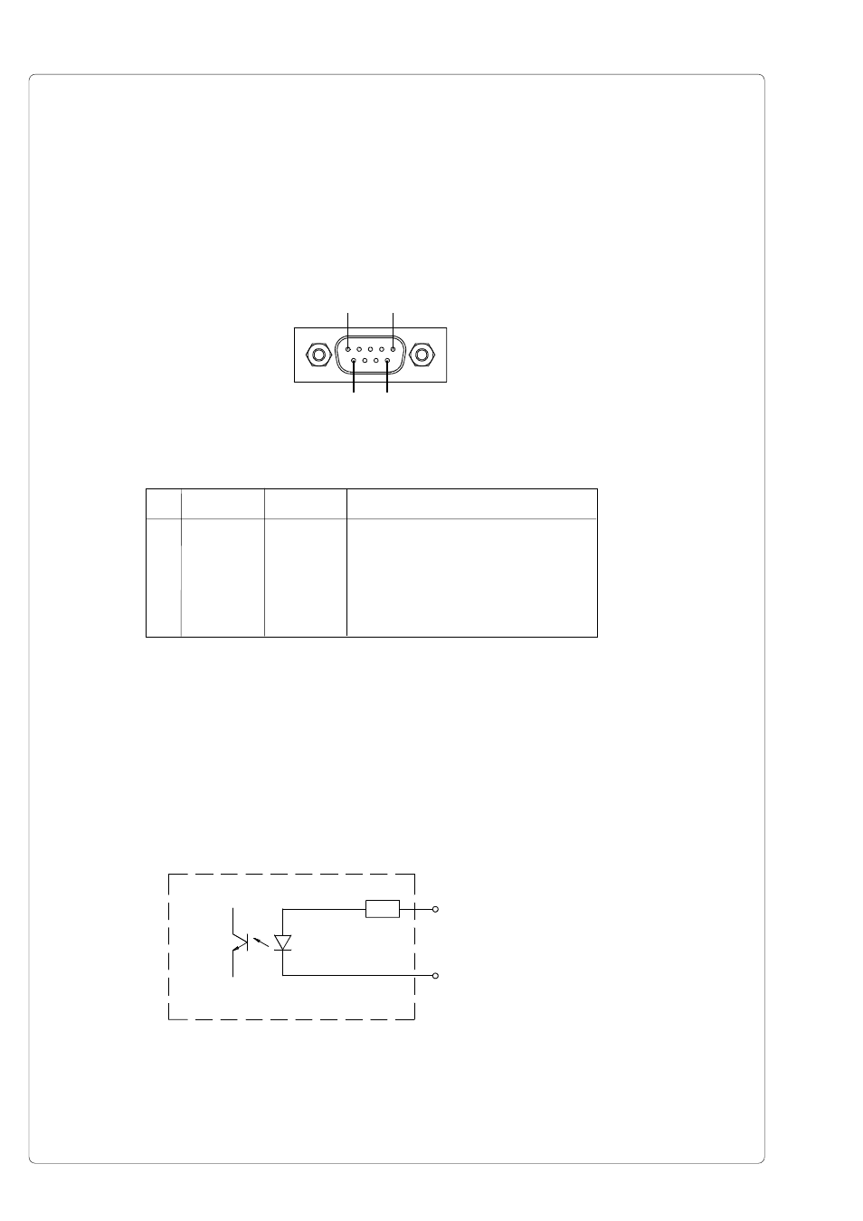
The printer provides a 9 pin port to connect a scanner. The scanner connector is only
supported at variations with applicator.
PIN 1
PIN 5
PIN 6
PIN 9
Pin Signal
Direction
Function
1
GND
Ground
2
DRW
input
GoodRead (Scan result)
3
XSCA
output
TopScan
6
24P
Operating voltage +24V, Si T 100mA
7
DRWR
(input)
GoodRead (revers line)
8
XSCAR
(output)
TopScan (revers line)
Table C-5 Signals of the scanner connector
Fig. C-10 Connector of the scanner (right side of the printer)
Circuit Diagram of Input and Output
The input is an optocoupler with a current limiting resistor of 2.2kW giving a voltage of 24V
in the input circuit.
Fig. C-11 Circuit of the input
PIN 2 - DRW
PIN 7 - DRWR