Brady PAM 3000 User Manual
Page 18
18
Printer-Applicator-System PAM 3000
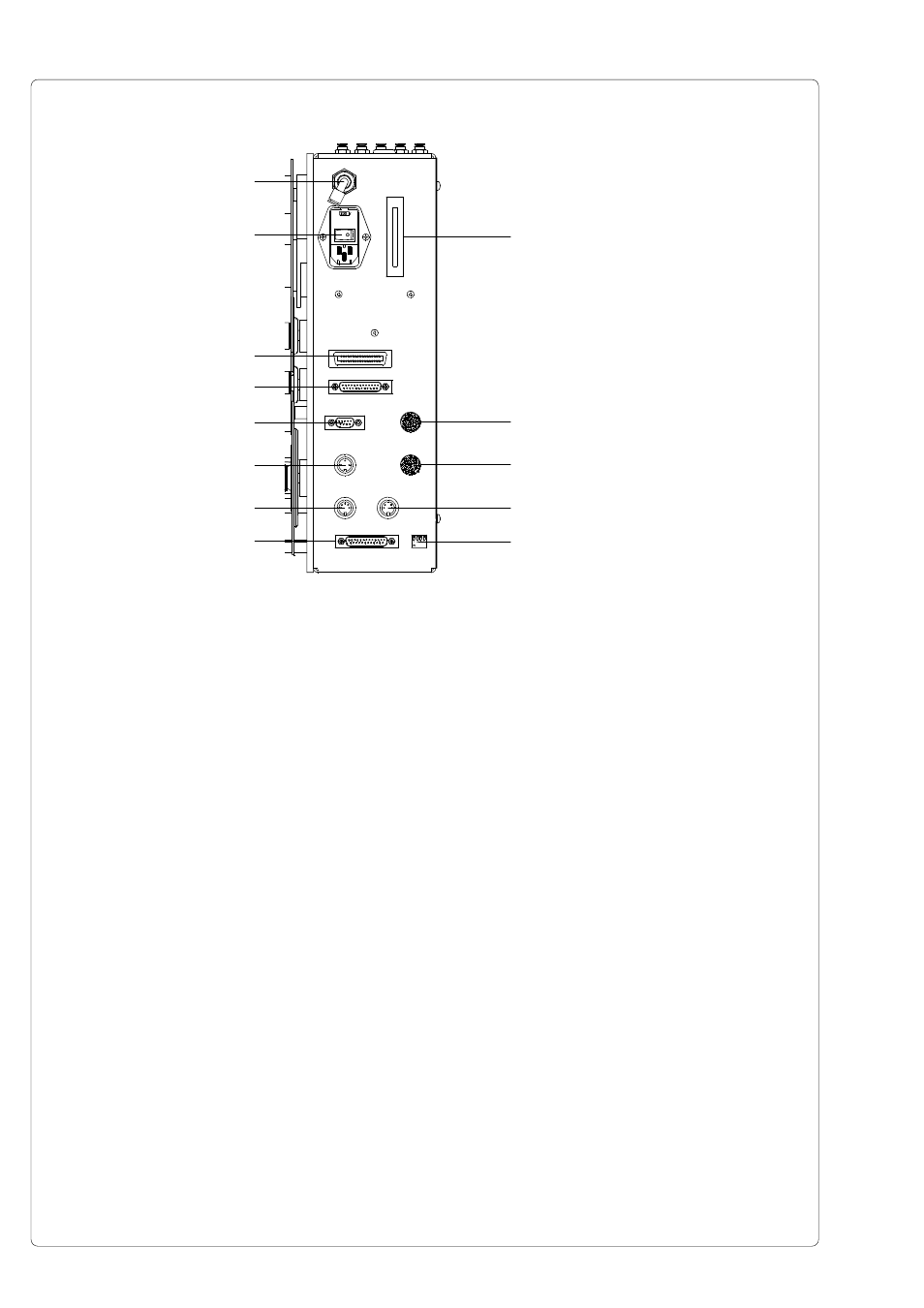
Fig. 4c
Side view
1 - Connector for the compressed air
2 - Power connector with power switch
3 - Parallel interface port
4 - Serial interface port
5 - Scanner connector
6 - Connector warning sensor transfer ribbon end
7 - Connector warning sensor label end
8 - PLC interface port
9 - DIP switches
10 - Connector warning light
11 - Silencer
12 - Memory card module slot
1
2
3
4
5
12
10
9
7
8
6
11
11