Warning sensors – Brady PAM 3000 User Manual
Page 54
Printer-Applicator-System PAM 3000
54
Warning Sensors
The sensors recognize, when the diameter of the label supply roll respectively the transfer
ribbon roll decreases below a preset threshold value.
NOTICE !
The messages of the sensors are only intended to inform the operator. They do
not influence the operation of the printer, i.e. the operation is not interrupted.
The messages will be shown by switching on the yellow lamp of the warning light (option).
The signals also can be sent to a control system by using the peripheral interface.
Warning Sensor Label End
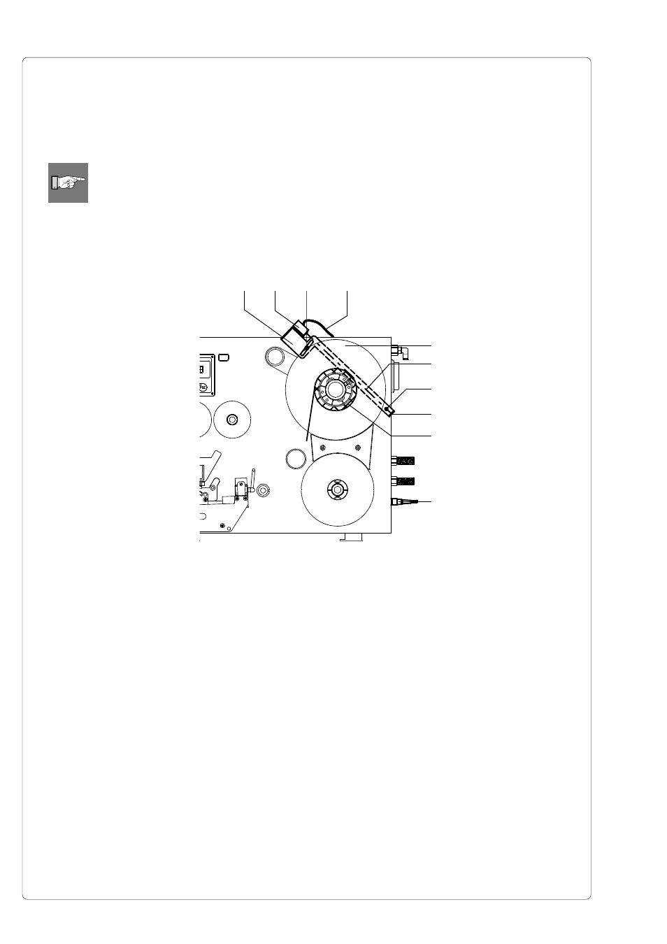
Mounting
1. Switch off the printer
2. Slide the sensor holder (1) with the warning sensor label end (2) behind the wind plate
(5) of the media supply hub.
3. Attach the sensor holder with the slotted head screw (7) and the hexagon socket head
screw (3) to the mounting plate. The hexagon socket head screw (3) must be used at
this side, where the elongated hole is located in the sensor holder.
4. Plug the cable (4) into the 5-pin connector (10) at the side of the frame of the printer.
Adjustment
With this setting the threshold diameter (84 to 110mm) for the warning message can be
adjusted.
1. Slide a label roll (9) with the intended threshold diameter onto the media supply hub.
2. Switch on the printer. The sensor (2) sends out a beam (6). If the label roll does not
interrupt the path of the beam, the beam is mirrored at the reflective foil (8) and
detected again by the sensor. In that case the LED at the sensor is on.
3. Loosen the hexagon socket head screw (3) and swing the sensor holder against the
axle of the media supply hub as near as possible. The LED at the sensor is off.
4. Slowly swing the sensor holder away from the axle until the LED at the sensor goes on.
5. Tighten the hexagon socket head screw (3).
Fig. 14f Warning sensor label end
1
2
3
4
8
7
6
5
9
10