Pin assignment of the serial interface connectors – Brady PAM 3000 User Manual
Page 69
C-1
Printer-Applicator-System PAM 3000
Appendix C - Pin Assignment of the Interface Connectors
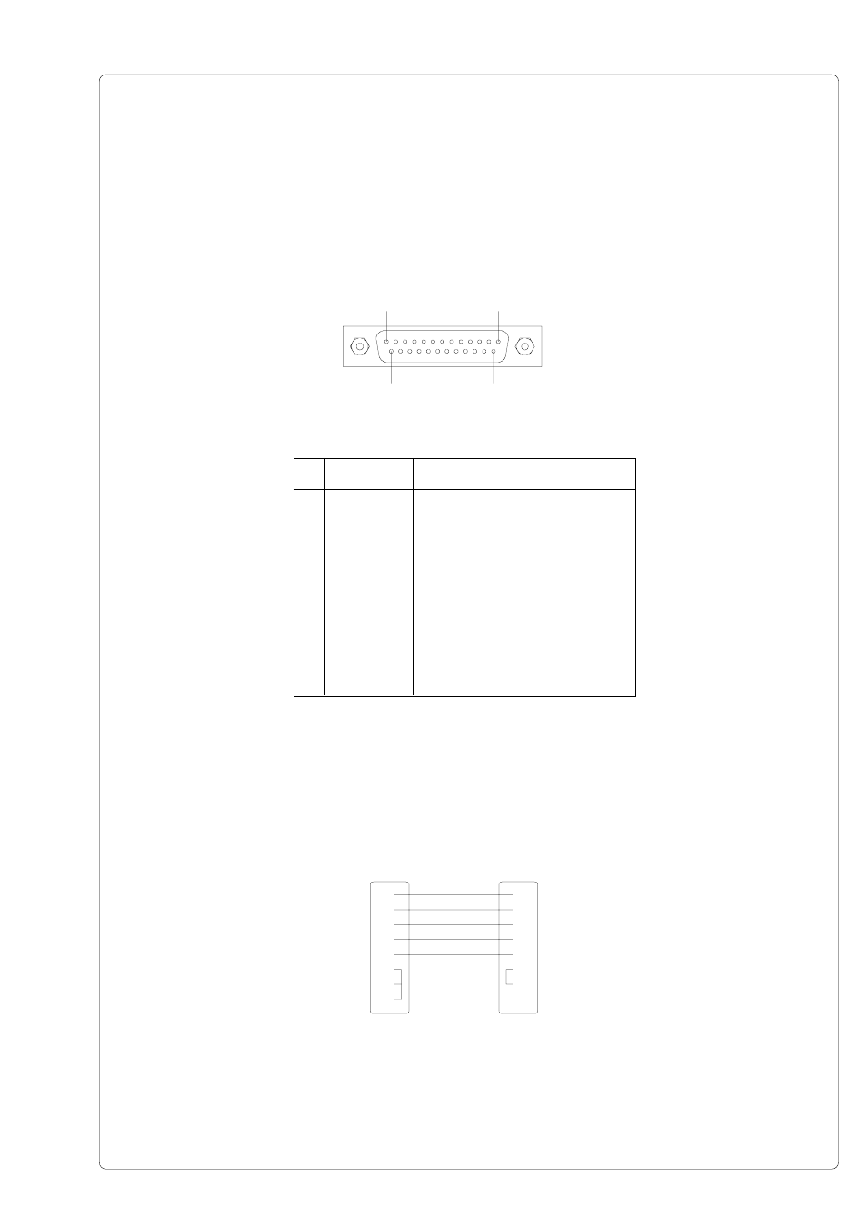
Pin Assignment of the Serial Interface Connectors
PAM 3000 provides a 25 pin SUB-D connector for the serial interfaces which are internally
available, i.e. RS-232, RS-422 and RS-485.
PIN 1
PIN 13
PIN 14
PIN 25
Pin
Signal
Function
1
CG
Protective Ground
2
TxD
Transmit Data (RS-232)
3
RxD
Receive Data (RS-232)
4
RTS
Request to send
5
CTS
Clear to send
7
GND
Logic Ground
9
TDATA+
Transmit Data (RS-422, RS-485)
10
TDATA-
Transmit Data (RS-422, RS-485)
18
RDATA+
Receive Data (RS-422, RS-485)
19
RDATA-
Receive Data (RS-422, RS-485)
20
DTR
Data Terminal Ready
Table C-1 Signals of the serial interface connector
Fig. C-1 Connector of the serial interface (side of the printer)
Fig. C-2 Interface cable with 25 pin computer connector for RS-232 with protocol
" ---" or "XON/XOFF"
Following some typical RS-232 interface cable configurations are shown. Note, that the pin
assignment may vary for different computers. If you have any problems with the connections,
contact the manufacturer of your computer on the pin assignment of the interface. Use the
pin assignment of the printer as shown in table C-1 to obtain a suitable cable.
PC
Printer
25 pin connector
25 pin plug
1
1
2
3
3
2
5
20
7
7
6
4
8
5
20