Brady PAM 3000 User Manual
Page 73
C-5
Printer-Applicator-System PAM 3000
Circuit Diagram of Inputs and Outputs
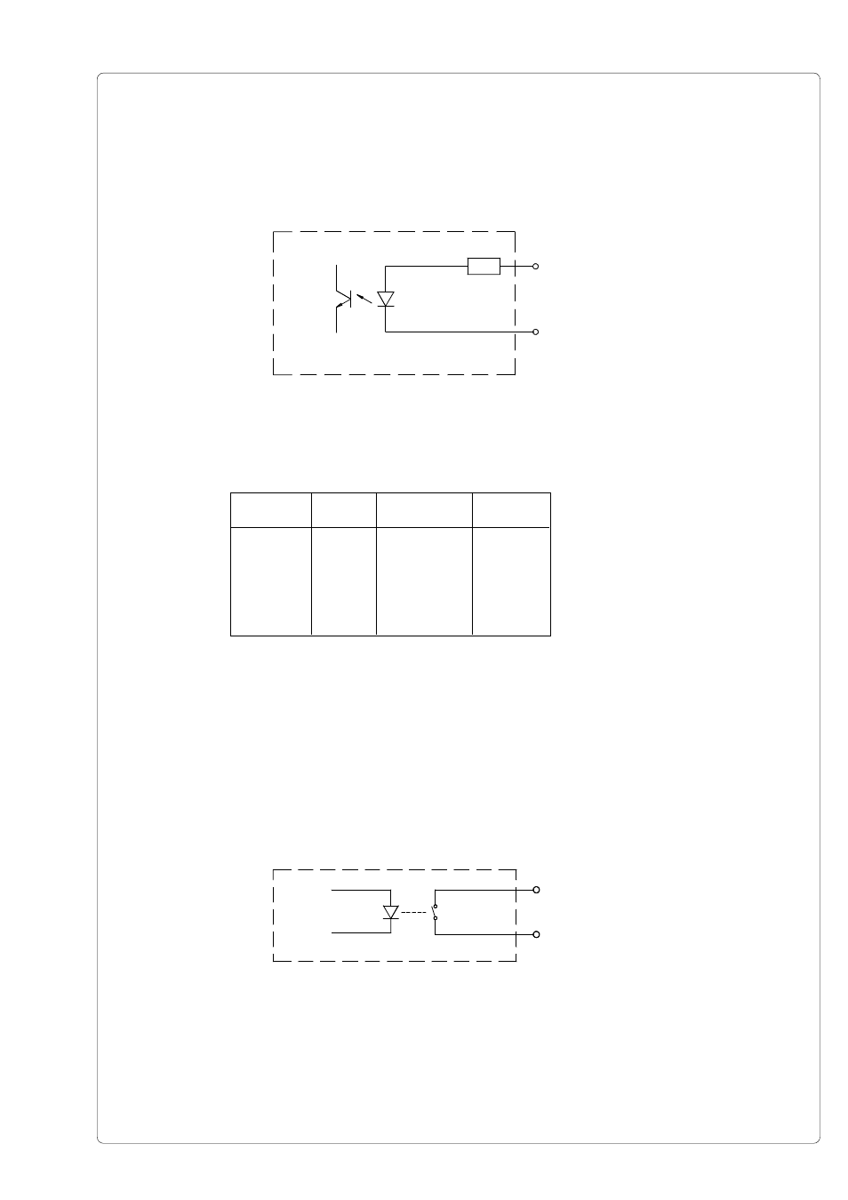
The inputs are optocouplers with a current limiting resistor of 2.2kW giving a voltage of 24V in
the input circuit.
Fig. C-8 Circuit of the inputs
X[IN]
X[IN]R
X[IN]
Pin
X[IN]R
Pin
EXF
9
EXFR
21
EUEB
10
EUEBR
22
STRT
11
STARTR
23
DRW
12
DRWR
24
ESP
13
ESPR
25
Table C-4 Input pairs of signals
For each signal X[IN] there is a separate reverse line X[IN]R via plug connector. From
that the following pairs of signals result :
All outputs are recognized through solid state relays. Their outputs are connected to one
another on one-side. The joint line is lead to the plug connector as a RÜL signal.
The switch function of the outputs is to open or close the contact between the joint line RÜL
and the respective output.
Electrical requirements : U
max
= 42V
I
max
= 100mA
Fig. C-9 Circuit of the ouputs
X[OUT]
RЬL