Rod seal installation -41, Cylinder head seal installation -41, Piston seal installation -41 – JLG 1500SJ Service Manual User Manual
Page 393
SECTION 5 - HYDRAULICS
3121262
– JLG Lift –
5-41
ASSEMBLY
NOTE: Prior to cylinder assembly, ensure that the proper
cylinder seal kit is used. See your JLG Parts Manual.
Apply a light film of hydraulic oil to all components
prior to assembly.
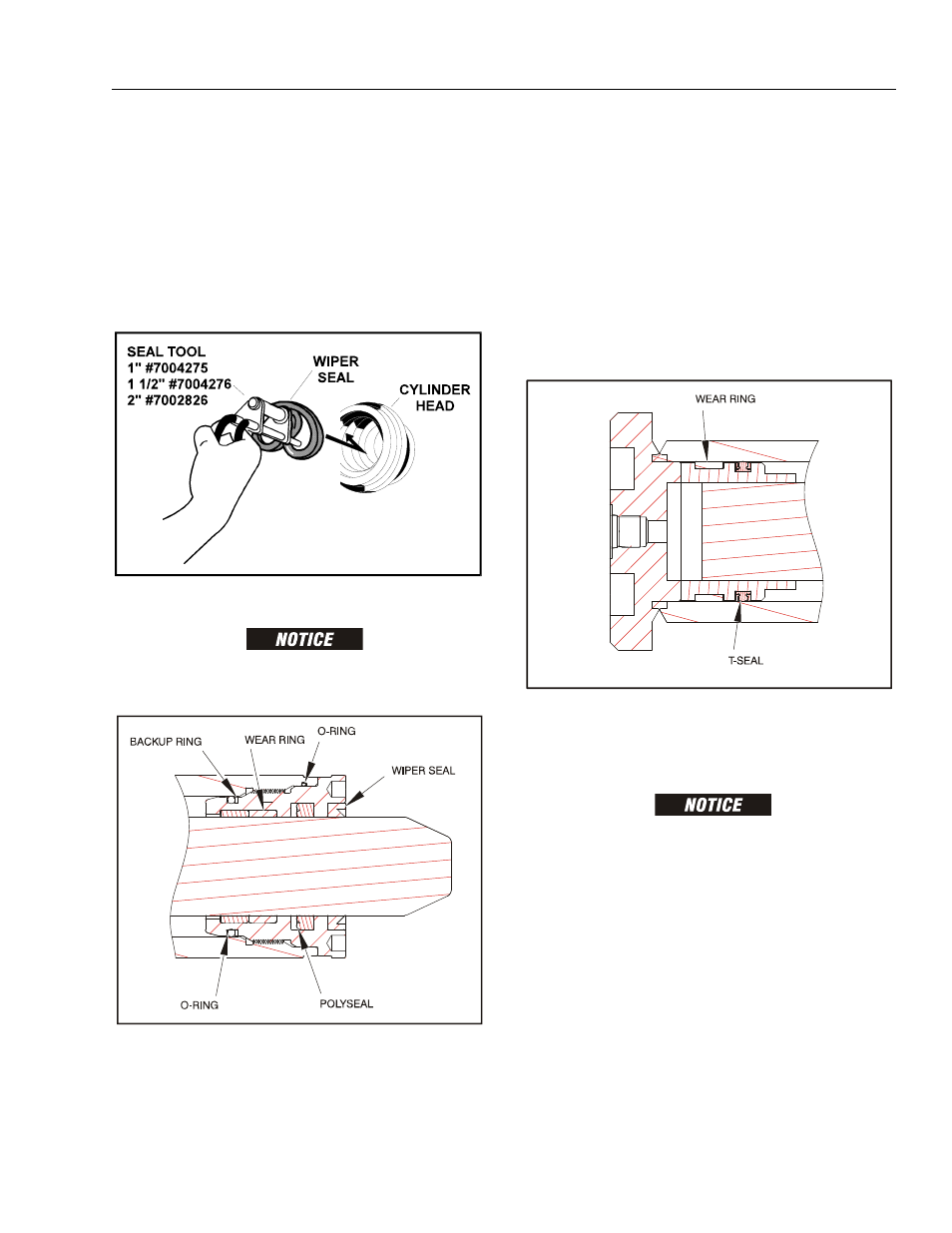
1. A special tool is used to install a new rod seal into
the applicable cylinder head gland groove.
WHEN INSTALLING NEW SEALS, ENSURE SEALS ARE INSTALLED
PROPERLY. IMPROPER SEAL INSTALLATION COULD RESULT IN
CYLINDER LEAKAGE AND IMPROPER CYLINDER OPERATION.
2. Use a soft mallet to tap a new wiper seal into the cyl-
inder head gland groove. Install a new wear ring into
the cylinder head gland groove.
3. Place a new O-rings and backup ring in the outside
diameter groove of the cylinder head and new wear
rings and polyseal in the inside diameter grooves of
the cylinder head.
4. Carefully install the head gland on the rod, ensuring
that the wiper and rod seals are not damaged or dis-
lodged. Push the head along the rod to the rod end.
5. Place a new wear ring and t-seal in the outer piston
diameter grooves. (A tube, with I.D. slightly larger
than the O.D.of the piston is recommended to install
the seal.)
6. Position the cylinder barrel in a suitable holding fix-
ture.
EXTREME CARE SHOULD BE TAKEN WHEN INSTALLING THE CYL-
INDER ROD, HEAD, AND PISTON. AVOID PULLING THE ROD OFF-
CENTER, WHICH COULD CAUSE DAMAGE TO THE PISTON AND
CYLINDER BARREL SURFACES.
7. With barrel clamped securely, and while adequately
supporting the rod, insert the piston end into the
barrel cylinder. Ensure that the piston seals are not
damaged or dislodged.
8. Continue pushing the rod into the barrel until the cyl-
inder head gland can be inserted into the barrel cyl-
inder.
9. Apply anti-seize lubricant to the threads and screw
the cylinder head gland into the barrel using a span-
ner wrench.
Figure 5-89. Rod Seal Installation
Figure 5-90. Cylinder Head Seal Installation
Figure 5-91. Piston Seal Installation