5 load sensing pin removal and installation, Load sensing pin removal and installation -50 – JLG 1500SJ Service Manual User Manual
Page 296
SECTION 4 - BOOM & PLATFORM
4-50
– JLG Lift –
3121262
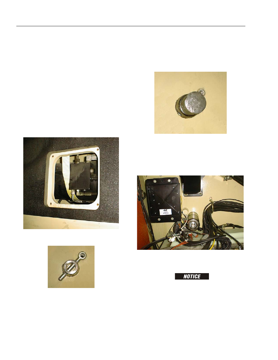
4.5 LOAD SENSING PIN REMOVAL AND
INSTALLATION
1. Place the machine on a firm, level surface.
NOTE: Replacing the load sensing pin requires the boom
sensors be re-calibrated. Make sure the machine is
in an area where this can be accomplished after
installation of the new pin.
2. Swing the engine tray out to gain access to the
sensing pin and retaining pin.
NOTE: The lift cylinder weighs 787 lbs. (357 kg.)
3. Run a nylon strap capable of supporting the weight
of the lift cylinder around the bottom of the cylinder.
Lift up on the strap to relieve the weight of the lift cyl-
inder on the load sensing pin.
4. Loosen and remove the bolt that secures the retain-
ing pin and remove the retaining pin.
5. Disconnect the wiring harness from the strain relief
connector at the opposite side of the load sensing
pin.
6. Use the Load Pin Removal Tool (JLG P/N 4846765)
to prevent the pin from being damaged, and use a
hammer to remove the pin. To make the tool refer to
Figure 4-13., Load Pin Removal Tool, JLG P/N
4846765. If the Load Pin Removal Tool is not avail-
able, use an arbor of the proper size (as shown
below). If excessive force is necessary to move the
pin, it may be necessary to carefully activate lift
using the auxiliary power switch to relieve lift cylin-
der weight from the load sensing pin.
7. When installing a new pin, make sure all of the holes
in the turntable and lift cylinder are aligned. If the
new load sensing pin does not push 1/2 to 3/4 of the
way in by hand, remove the pin and align the holes
better. Also make sure the pin is installed with the
strain relief connector opposing the pin orientation
bar as shown. Refer to Pivot Pin Installation.
8. Using an oak block, carefully tap the pin until it is
fully installed. Secure the pin in place with the retain-
ing pin and retaining pin bolt.
DO NOT TAP ON THE CENTER OF THE PIVOT PIN.
9. Connect the wiring harness to the strain relief con-
nector and re-calibrate the boom sensors.