JLG 1500SJ Service Manual User Manual
Page 295
SECTION 4 - BOOM & PLATFORM
3121262
– JLG Lift –
4-49
40. Push the inner mid boom assembly the rest of the
way into the boom base section, adjusting the lifting
device as necessary to keep the weight balanced.
41. Apply JLG Threadlocker P/N 0100011 to the bolts
and install the side and upper wear pads into the
boom base section. Torque the bolts to 50 ft.lbs. (68
Nm).
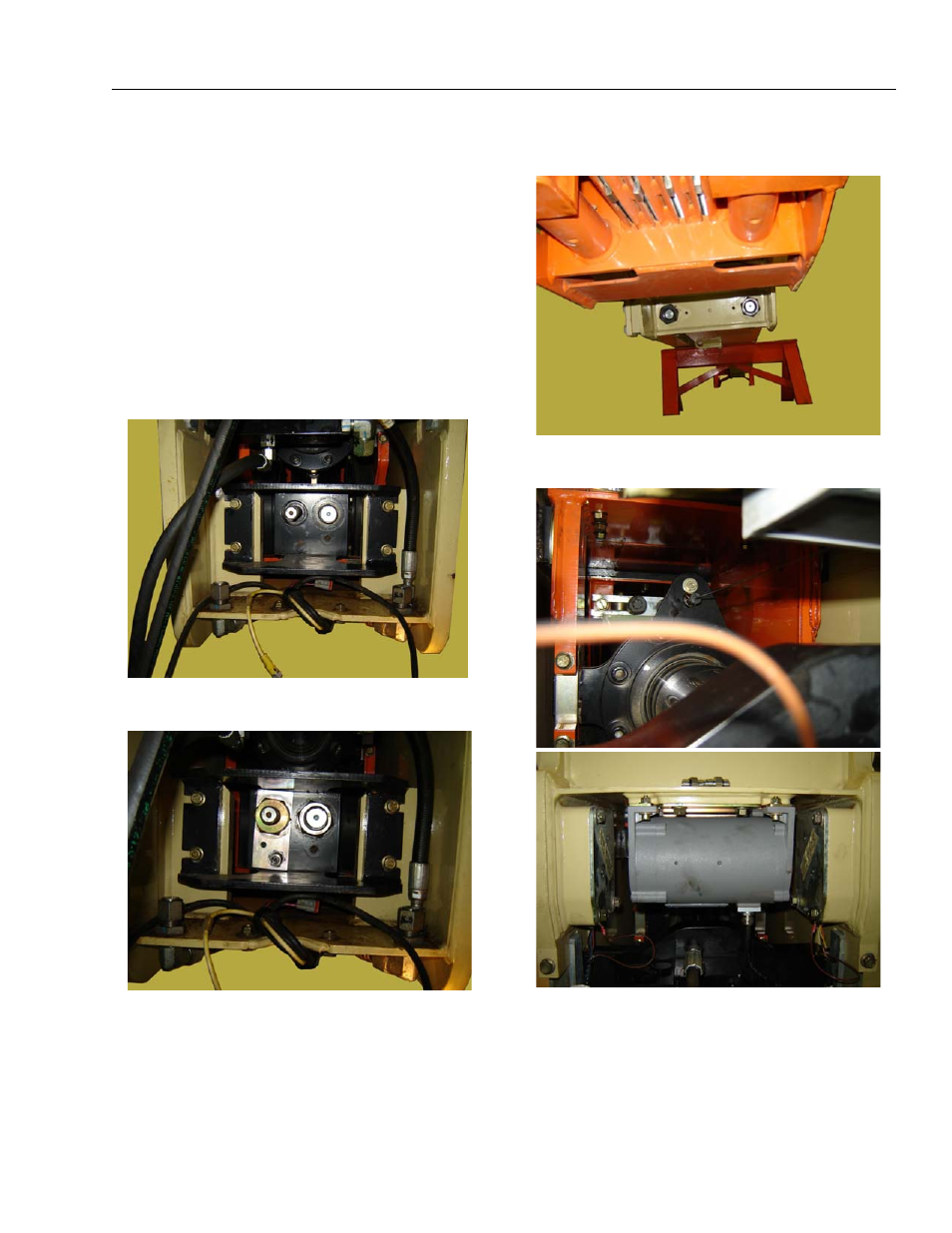
42. Install the boom transport length sensor on the side
of the boom base section.
43. Attach the powertrack tubes.
44. If necessary, attach a source of auxiliary hydraulic
power and retract the boom enough to allow instal-
lation of the cable adjustment plate at the rear of the
base boom section and install the plate.
45. Install the broken cable sensor and the outer mid
extend cable adjustment nuts.
46. Install the outer mid retract cable adjustment nuts at
the front of the boom base section.
47. Install the boom length sensors and angle sensors
as tagged during removal.
48. Connect the hydraulic hoses to the telescope cylin-
der as tagged during removal.
49. Adjust the boom cables. Refer to Section 4.16 - Wire
50. Perform a boom calibration as described in Section
6 under Calibrating the Boom Sensors.