Axle lockout cylinder, Axle lockout cylinder -9, Cylinder barrel support -9 – JLG 1500SJ Service Manual User Manual
Page 361: Cap screw removal -9, Cylinder rod support -9
SECTION 5 - HYDRAULICS
3121262
– JLG Lift –
5-9
Axle Lockout Cylinder
DISASSEMBLY
DISASSEMBLY OF THE CYLINDER SHOULD BE PERFORMED ON A
CLEAN WORK SURFACE IN A DIRT FREE WORK AREA.
1. Connect a suitable auxiliary hydraulic power source
to the cylinder port block fitting.
DO NOT FULLY EXTEND CYLINDER TO THE END OF STROKE.
RETRACT CYLINDER SLIGHTLY TO AVOID TRAPPING PRESSURE.
2. Operate the hydraulic power source and extend the
cylinder. Shut down and disconnect the power
source. Adequately support the cylinder rod, if appli-
cable.
3. Remove the counterbalance valves from the cylinder
port block. Discard o-rings.
4. If necessary, remove the bleeder valve.
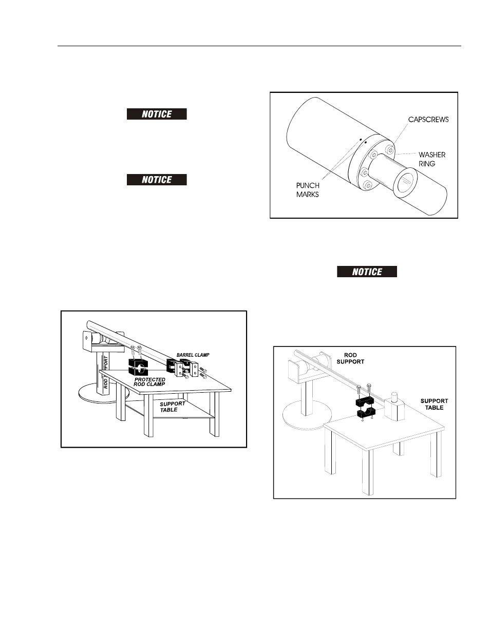
5. Place the cylinder barrel into a suitable holding fix-
ture.
6. Mark cylinder head and barrel with a center punch
for easy realignment. Using an allen wrench, loosen
the cylinder head retainer capscrews, and remove
capscrews from cylinder barrel.
7. Attach a suitable pulling device to the cylinder rod
end.
EXTREME CARE SHOULD BE TAKEN WHEN REMOVING THE CYL-
INDER ROD, HEAD, AND PISTON. AVOID PULLING THE ROD OFF-
CENTER, WHICH COULD CAUSE DAMAGE TO THE PISTON AND
CYLINDER BARREL SURFACES.
8. With the barrel clamped securely, carefully withdraw
the complete rod assembly from the cylinder barrel.
Figure 5-15. Cylinder Barrel Support
Figure 5-16. Cap Screw Removal
Figure 5-17. Cylinder Rod Support