7 master clock switching characteristics, 8 transmit switching characteristics, 9 receive switching characteristics – Cirrus Logic CS61884 User Manual
Page 59
CS61884
DS485F3
59
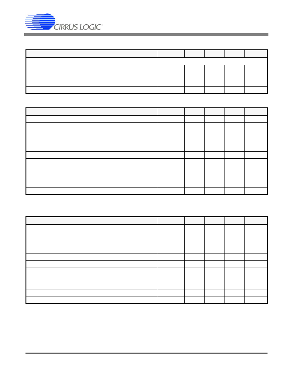
19.7 Master Clock Switching Characteristics
19.8 Transmit Switching Characteristics
19.9 Receive Switching Characteristics
* All parameters guaranteed by production, characterization or design.
Notes: 20. Output load capacitance = 50pF.
21. MCLK is not active.
22. Parameters guaranteed by design and characterization.
Parameter
Symbol
Min.
Typ
Max
Units
MASTER CLOCK (MCLK)
Master Clock Frequency
E1 Modes
MCLK
2.048
MHz
Master Clock Frequency
T1/J1 Modes
MCLK
1.544
MHz
Master Clock Tolerance
-
-100
+100
ppm
Master Clock Duty Cycle
-
40
50
60
%
Parameter
Symbol
Min.
Typ
Max
Units
E1 TCLK Frequency
1/t
pw2
-
2.048
-
MHz
E1 TPOS/TNEG Pulse Width (RZ Mode)
236
244
252
nS
T1/J1 TCLK Frequency
1/t
pw2
-
1.544
-
MHz
TCLK Tolerance (NRZ Mode)
-50
-
50
PPM
TCLK Duty Cycle
t
pwh2
/t
pw2
-
-
90
%
TCLK Pulse Width
20
-
-
nS
TCLK Burst Rate
Note
-
-
20
MHz
TPOS/TNEG to TCLK Falling Setup Time (NRZ Mode)
t
su2
25
-
-
nS
TCLK Falling to TPOS/TNEG Hold time (NRZ Mode)
t
h2
25
-
-
nS
TXOE Asserted Low to TX Driver HIGH-Z
-
-
1
μS
TCLK Held Low to Driver HIGH-Z
Note
8
12
20
μS
Parameter
Symbol
Min.
Typ
Max
Units
RCLK Duty Cycle
40
50
60
%
E1 RCLK Pulse Width
196
244
328
nS
E1 RPOS/RNEG Pulse Width (RZ Mode
200
244
300
nS
E1 RPOS/RNEG to RCLK rising setup time
t
su
150
244
-
nS
E1 RPOS/RNEG to RCLK hold time
t
h
200
244
-
nS
T1/J1 RCLK Pulse Width
259
324
388
nS
T1/J1 RPOS/RNEG Pulse Width (RZ Mode)
250
324
400
nS
T1/J1 POS/RNEG to RCLK rising setup time
t
su
150
324
-
nS
T1/J1 RPOS/RNEG to RCLK hold time
t
h
200
324
-
nS
RPOS/RNEG Output to RCLK Output (RZ Mode)
-
-
10
nS
Rise/Fall Time, RPOS, RNEG, RCLK, LOS outputs
t
r
, t
f
-
-
85
nS