4 select-dr-scan, 5 capture-dr, 6 shift-dr – Cirrus Logic CS61884 User Manual
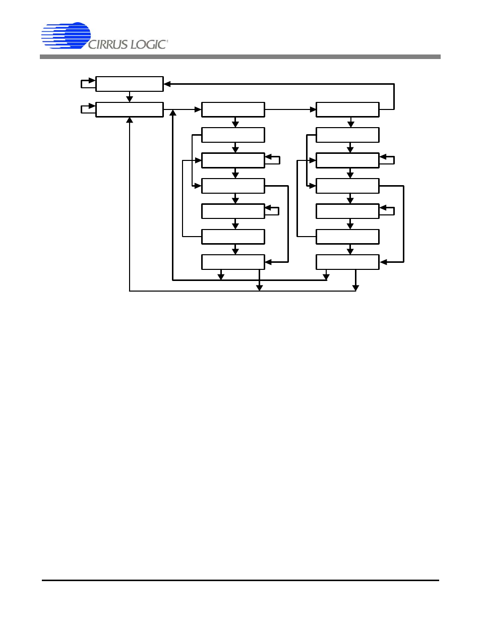
Page 46: 7 exit1-dr, 8 pause-dr, 9 exit2-dr, 10 update-dr, Figure 16. tap controller state diagram, Figure 16, The value shown next to each state tran
CS61884
46
DS485F3
16.1.4 Select-DR-Scan
This is a temporary controller state.
16.1.5 Capture-DR
In this state, the Boundary Scan Register captures
input pin data if the current instruction is EXTEST
or SAMPLE/PRELOAD.
16.1.6 Shift-DR
In this controller state, the active test data register
connected between TDI and TDO, as determined
by the current instruction, shifts data out on TDO
on each rising edge of TCK.
16.1.7 Exit1-DR
This is a temporary state. The test data register se-
lected by the current instruction retains its previous
value.
16.1.8 Pause-DR
The pause state allows the test controller to tempo-
rarily halt the shifting of data through the current
test data register.
16.1.9 Exit2-DR
This is a temporary state. The test data register se-
lected by the current instruction retains its previous
value.
16.1.10 Update-DR
The Boundary Scan Register is provided with a
latched parallel output to prevent changes while
data is shifted in response to the EXTEST and
SAMPLE/PRELOAD instructions. When the TAP
controller is in this state and the Boundary Scan
Register is selected, data is latched into the parallel
output of this register from the shift-register path
on the falling edge of TCK. The data held at the
latched parallel output changes only in this state.
1
0
Test-Logic-Reset
Run-Test/Idle
Select-DR-Scan
Capture-DR
Shift-DR
Exit1-DR
Pause-DR
Exit2-DR
Update-DR
Select- I R-Scan
Capture- IR
Shift- IR
Exit1- IR
Pause- IR
Exit2- IR
Update- I R
0
1
1
1
1
1
1
1
1
1
1
1
1
1
1
0
0
0
0
0
0
0
0
0
0
0
0
0
1
0
Figure 16. TAP Controller State Diagram