Jtag support, 1 tap controller, 1 jtag reset – Cirrus Logic CS61884 User Manual
Page 45: 2 test-logic-reset, 3 run-test-idle, 2 test-logic-reset 16.1.3 run-test-idle, Figure 15. test access port architecture
CS61884
DS485F3
45
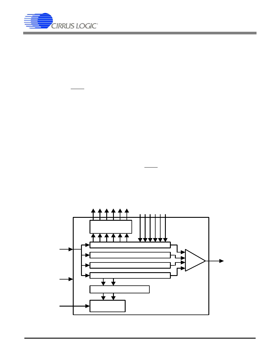
16. JTAG SUPPORT
The CS61884 supports the IEEE Boundary Scan
Specification as described in the IEEE 1149.1 stan-
dards. A Test Access Port (TAP) is provided that
consists of the TAP controller, the instruction reg-
ister (IR), by-pass register (BPR), device ID regis-
ter (IDR), the boundary scan register (BSR), and
the 5 standard pins (TRST, TCK, TMS, TDI, and
TDO). A block diagram of the test access port is
shown in
. The test clock input (TCK) is
used to sample input data on TDI, and shift output
data through TDO. The TMS input is used to step
the TAP controller through its various states.
The instruction register is used to select test execu-
tion or register access. The by-pass register pro-
vides a direct connection between the TDI input
and the TDO output. The device identification reg-
ister contains an 32-bit device identifier.
The Boundary Scan Register is used to support test-
ing of IC inter-connectivity. Using the Boundary
Scan Register, the digital input pins can be sampled
and shifted out on TDO. In addition, this register
can also be used to drive digital output pins to a
user defined state.
16.1 TAP Controller
The TAP Controller is a 16 state synchronous state
machine clocked by the rising edge of TCK. The
TMS input governs state transitions as shown in
. The value shown next to each state tran-
sition in the diagram is the value that must be on
TMS when it is sampled by the rising edge of TCK.
16.1.1 JTAG Reset
TRST resets all JTAG circuitry.
16.1.2 Test-Logic-Reset
The test-logic-reset state is used to disable the test
logic when the part is in normal mode of operation.
This state is entered by asynchronously asserting
TRST or forcing TMS High for 5 TCK periods.
16.1.3 Run-Test-Idle
The run-test-idle state is used to run tests.
parallel latched
output
Boundary Scan Data Register
Device ID Data Register
Bypass Data Register
Instruction (shift) Register
TAP
Controller
parallel latched output
TDI
TCK
Digital output pins
Digital input pins
JTAG BLOCK
MUX
TDO
TMS
Figure 15. Test Access Port Architecture