WIKA CF1H User Manual
Page 65
Operating Instructions Temperature Indicating Controller CF1H
V 1.2
•
01/2007
- 65 -
Action
: ON/OFF action
Hysteresis setting range
When thermocouple or RTD input, 0.1 … 100.0 °C (°F)
When DC input, 1 … 1000
(Decimal point place follows the selection.)
Output
: Relay contact 1a
Control capacity, 250 V AC, 3 A (resistive load)
250 V AC, 1 A (inductive load cosø =0.4)
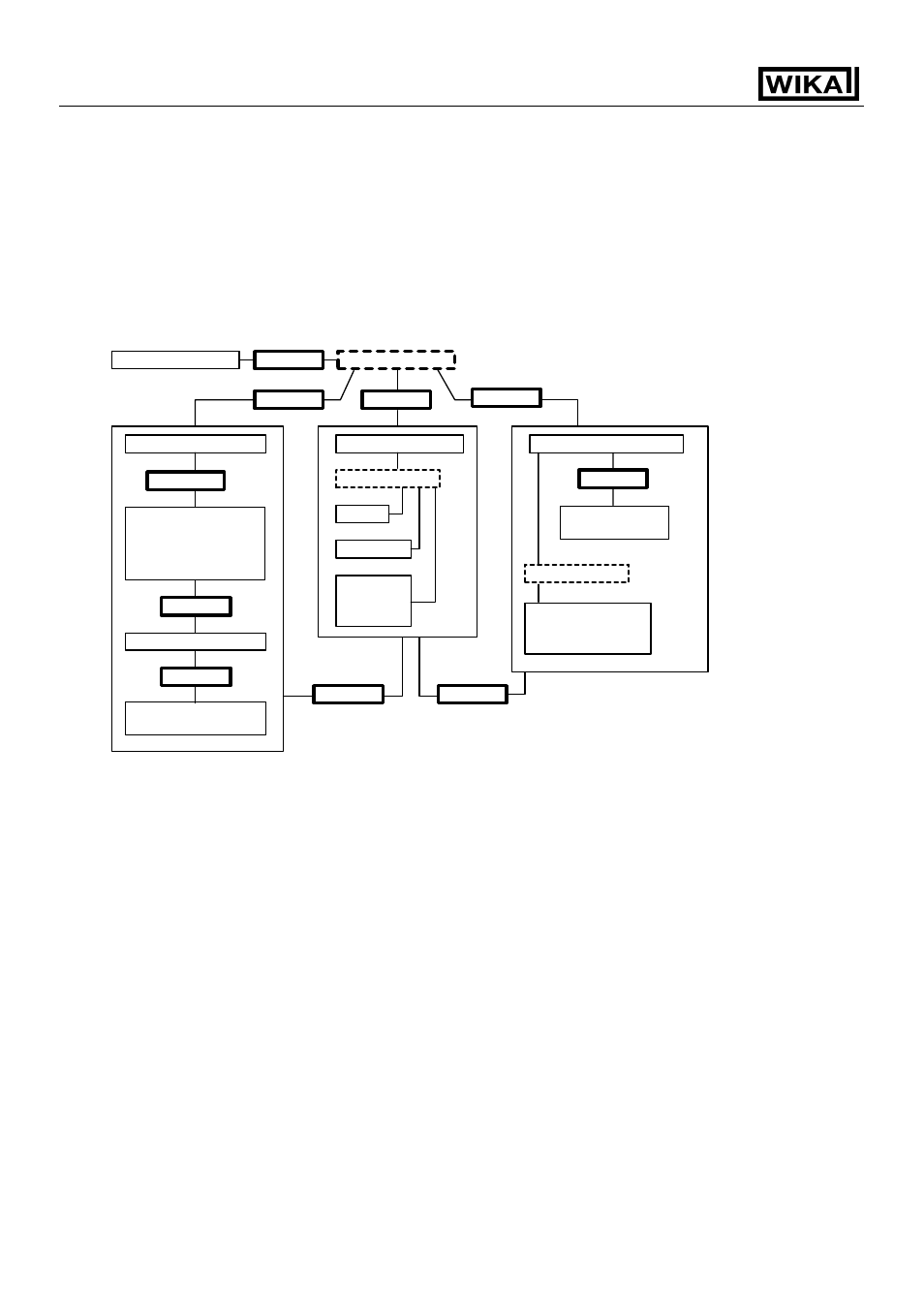
Circuit insulation configuration
(*1) When both Main output and Cooling output are Current output type or
Non-contact voltage output type (the SSR drive), A to B is non-isolated.
(*2) When Main output is Current output type or Non-contact voltage output type
(the SSR drive), A to F and A to G are non-isolated.
When Cooling output is Current output type or Non-contact voltage output type
(the SSR drive), B to F and B to G are non-isolated.
Insulation resistance
10M
Ω or greater at 500Vdc
Insulation test must not be carried out between A-B in the case of Circuit
insulation configuration (*1), and between A-F, B-F, A-G, B-G, C-D-E and
F-G in the case of Circuit insulation configuration (*2) because they are
non-isolated.
Dielectric strength
Between input terminal and ground terminal, 1.5 kV AC for 1 minute
Between input terminal and power terminal, 1.5 kV AC for 1 minute
Between power terminal and ground terminal, 1.5 kV AC for 1 minute
Between output terminal and ground terminal, 1.5 kV AC for 1 minute
Between output terminal and power terminal, 1.5 kV AC for 1 minute
Ground terminal
Isolated
Power source
Main output
CPU
Communication part
Isolated
Cooling output,
Alarm 2 output or
Loop break alarm
output
Alarm 1 output
Isolated
Isolated
Heater burnout
alarm output
Isolated
Isolated
Isolated
Non-isolated
Input
CT input
External
setting
input
Transmission
output
Non-isolated
Setting value
memory number
external change
(*2)
(*1)
Isolated
Isolated
Isolated
(*2)
G
A
B
C
D
E
F