Warning – WIKA CF1H User Manual
Page 59
Operating Instructions Temperature Indicating Controller CF1H
V 1.2
•
01/2007
- 59 -
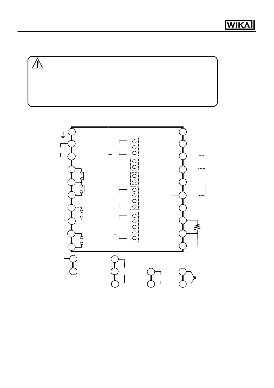
11. Wiring connection
Warning
Turn the power supply to the instrument off before wiring or checking.
Working or touching the terminal with the power switched on may result
in Electric Shock, which can cause severe injury or death.
Moreover, the instrument must be grounded before the power supply to the
instrument is turned on.
11.1 Terminal arrangement
[Fig. 11.1-1]
The terminal block of this instrument is designed to be wired from the left side.
The lead wire must be inserted from the left side of the terminal, and fastened with the terminal screw.
Dotted lines shows options (page 67), no terminal is equipped if it is not specified.
If the Alarm 2 (pattern end 2 output) is applied with a combination of the Loop break alarm output, the
output terminal is common.
1
4
H
7
8
+
9
10
OUT2
(DR,DS,DA)/
A2/Pattern end
2/LA/P24
100 to 240Vac
or 24Vac/dc
2
18
19
18
19
11
12
14
15
16
TC
RTD
C
Ground
5
OUT1
(R/M)
5 +
6
OUT1
(S/M or A/M)
A1/Pattern end 1
EA or EV
+
RS-232C
[RS-485]
TX [YA(-)]
RX [YB(+)]
b
0
b
1
b
2
COM
B
B
A
SM
W or W3
CT2
CT1
+
18
19
+
Vdc
18
19
+
mAdc
17
3
13
6
L
17
20
+
TA or TV
+