Notices – WIKA CF1H User Manual
Page 60
Operating Instructions Temperature Indicating Controller CF1H
V 1.2
•
01/2007
- 60 -
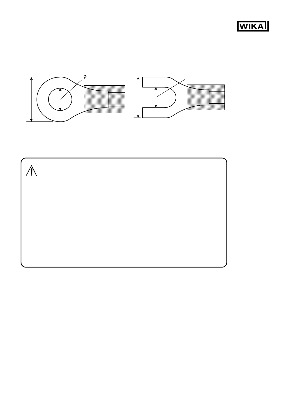
n Recommended terminal
Use a solderless terminal with insulation sleeve to fit to M3 screw as shown below.
11.2 Wiring connection examples
Notices
• Use a thermocouple and compensating lead wire according to the input
specifications of this controller.
• Use a 3-wire RTD system according to the input specifications of this controller.
• This controller has no built-in power switch or fuse. It is necessary
to install them manually (IEC approved, 100 V AC 5 A or 220 V AC 5 A)
in the circuit near the external controller.
• In the case of 24 V DC, do not confuse the polarity.
• For the relay contact output type, use an external auxiliary electromagnetic
switch to protect the built-in relay contact.
• When wiring, keep the input wire (Thermocouple, RTD, etc.) away from AC
source and the load wire to avoid external interference.
• Use a thick wire (1.25 to 2.0 mm
2
) for the earth ground.
3.2mm
5.8mm or less
3.2mm
5.
8mm or less