2 connecting the audio control port, Connecting the audio control port, On 6.2 – Kramer Electronics VP-747 User Manual
Page 22: Figure 7
VP-747 - Connecting the VP-747 Control Ports
17
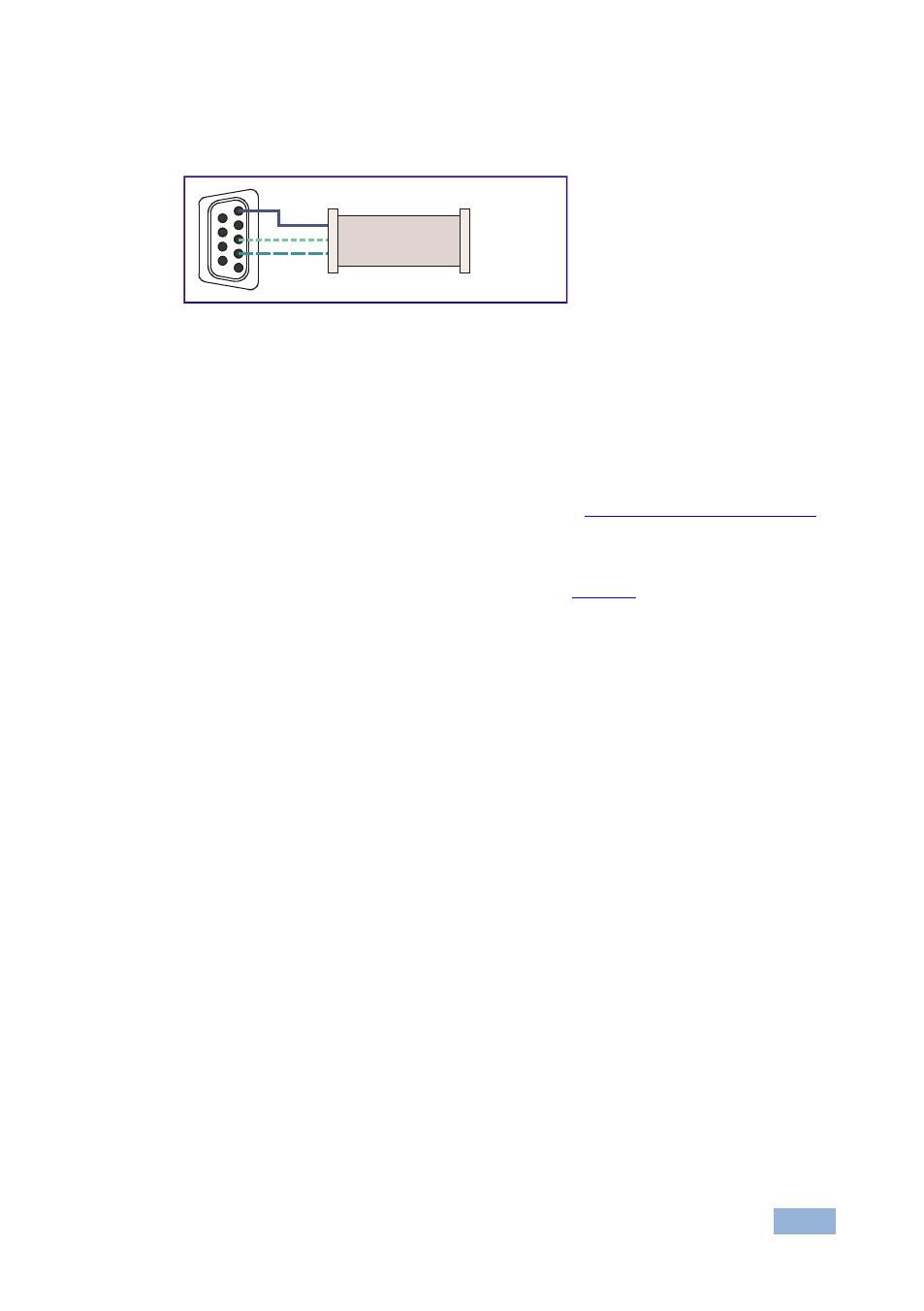
Method A above) only requires pins 2, 3 and 5 to be connected, you are free to
decide whether to connect only these 3 pins or all 9 pins.
Figure 7: Straight Cable RS-232 Connection with a Null Modem Adapter
6.2
Connecting the Audio Control Port
The Kramer
VP-727A Audio Switcher operates in conjunction with the VP-747.
When connected, the audio switcher signals follow the video signals.
See the separate VP-727A user manual on our Web site a
To connect the
VP-747
to the
Kramer
VP-727A Audio Switcher via the TO AUDIO
UNIT RS-485 port, as illustrated in the example in
, do the following:
•
Connect the “A” (+) PIN on the AUDIO CONTROL RS-485 rear panel port of
the
VP-747 to the A (+) PIN on the RS-485 rear panel port of the VP-727A
unit
•
Connect the “B” (-) PIN on the AUDIO CONTROL RS-485 rear panel port of
the
VP-747 to the B (-) PIN on the RS-485 rear panel port of the VP-727A
unit
•
If shielded twisted pair cable is used, the shield may be connected to the “G”
(Ground) PIN on one of the units
1
2
6
3
7
4
8
5
9
to PC
Null-Modem
Adapter