Kramer Electronics VP-747 User Manual
Page 13
8
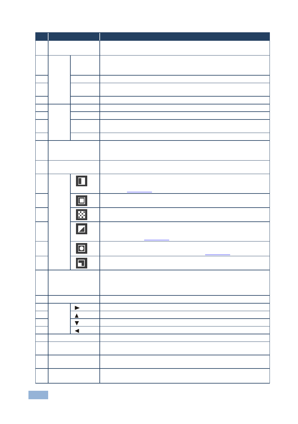
VP-747 - Overview
#
Feature
Function
1
IR Receiver/LED
Green when ON; red when OFF
OFF in this case means that the outputs and the front-panel are disabled
2
PR
EVI
EW
B
ut
to
ns
INPUTS
Selects the video source (from 1 to 8) for the Preview output
From the five BNC (universal) inputs for each of the inputs. The INPUT
buttons 1 and 2 can also select the DVI/HDMI sources
3
PIP
Toggles the picture-in-picture function on and off on the Preview output
4
BLANK
Toggles between a blank screen and the selected input on the preview
output
5
FREEZE
Freezes the output video image (toggle) on the Preview output
6
P
R
OGR
A
M
B
ut
to
ns
INPUTS
Selects the video source (from 1 to 8) for the Program output
7
FREEZE
Freezes the output video image (toggle) on the Program output
8
BLANK
Toggles between a blank screen and the selected input on the Program
output
9
PIP
Toggles the picture-in-picture function on and off on the Program output
10 TAKE Button
Pressing TAKE causes the transition to occur
The effect is only seen in PROGRAM Mode. The PREVIEW screen
blanks during the transition
11 FADE Button
Selects a dissolved transition from the PREVIEW output to the
PROGRAM output
12
TR
A
N
S
IT
IO
N
B
ut
tons
Selects a
WIPE transition effect
To choose the direction from where the effect starts: “left to right”, “right to left”, “up” or
“down”, see
13
Section 8.1.3
Selects a
SQUARE transition effect
14
Selects a
CHESSBOARD transition effect
15
Selects a
DIAGONAL transition effect
To choose the direction from where the effect starts: “top left”, “bottom left”, “top right”
or “bottom right”, see
16
Section 8.1.3
Selects a
CIRCLE transition effect
To choose the direction of the effect: “in” or “out”, see
17
Section 8.1.3
Selects a
CORNER transition effect
18 CUT Button
Selects an instantaneous transition from the PREVIEW output to the
PROGRAM output
Only for setting up the unit for the effect. The effect only occurs when the Take button
is pressed
19 OSD Button
Activates/deactivates access to the OSD Menu on the Preview output
20
N
AV
IGA
TION
B
ut
to
ns
Toggles within each level 2 command/increases the range by one step
21
Moves up one step (in the same level) in the OSD menu
22
Moves down one step (in the same level) in the OSD menu
23
Toggles within each level 2 command/decreases the range by one step
24 ENTER Button
Moves to the next level in the OSD menu
25 MENU Button
Displays the OSD Menu screen (or moves to the previous level in the
OSD menu)
26 LCD STATUS
Display
Displays the status of the unit, and is used for menu navigation
27 PANEL LOCK
Button
Locks/unlocks the front panel
Press and hold for about 2 seconds to toggle