Home screen navigation, Pump status, Station discharge status – Bell & Gossett 10-001-275 XLS Integrated Pump Controller User Manual
Page 9
9
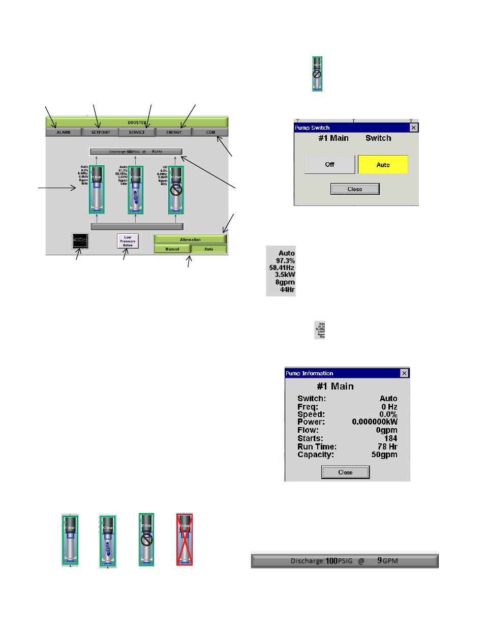
Home Screen Navigation
The Booster home screen has been designed to mimic
the look of the configured booster and to allow for quick
visual cues for ease of navigation.
Figure 9: H o m e Screen Navigation
The Home screen has various buttons and information
blocks detailed below.
1. Pump Status
2. Station Discharge Status
3. Modes of Operation
4. Alternation Set-up
5. Low Pressure Override
6. System View
7. Alarm Tab
8. Setpoint Tab
9. Service Tab
10. Energy Tab
11. Communications Tab
PUMP STATUS
The Individual pumps for each will have multiple means
of status display both visually and with data.
1. Visual Pump Symbols:
Figure 10: P u m p S ym b o l s
a. By tapping
, in either Idle or Auto Modes, an
enhanced screen shown in Figure 11 will appear to
set individual pump status.
Figure 11: Pump Switch Screen
2. Pump Status Detail:
Figure 1 2 : P u m p D e t a i l
a. By tapping
, an enhanced screen shown in
Figure 13 will appear with more detailed
information.
Figure 13: P u m p I n f o r m a t i o n
STATION DISCHARGE STATUS
The station discharge status bar will display the current
discharge conditions for the station.
Figure 14: Station Discharge Status
3
5
6
11
10
7
8
2
4
1
Stand-By
Running
Off
Alarm
- Status
- Percent Speed
- Hertz
- kW
- Flow Rate
- Total runtime
9