Alarms – Bell & Gossett 10-001-275 XLS Integrated Pump Controller User Manual
Page 13
13
scaling for the channel. The exception here is
the KW reading, which is an absolute number
because KW is read directly, rather than
scaled.
Click “Channels” to access the calibration
screen directly from the “Configure Data”
screen.
This screen is accessible also from “Setup”-
>”Options Setup” and is discussed in detail
in that section.
e. Technical Overview
By tapping [Technical Overview] a new detail
screen shown in Figure 25 appears showing
system operation.
Figure 25: Technical Overview
This screen shows an overview of the
configuration of the station. Most data that is
necessary for tuning is shown, and the
settings page for the information can be
accessed by touching the value. For
technicians, the fields available on this
screen should be fairly self-explanatory.
However, some fields can use some
clarification:
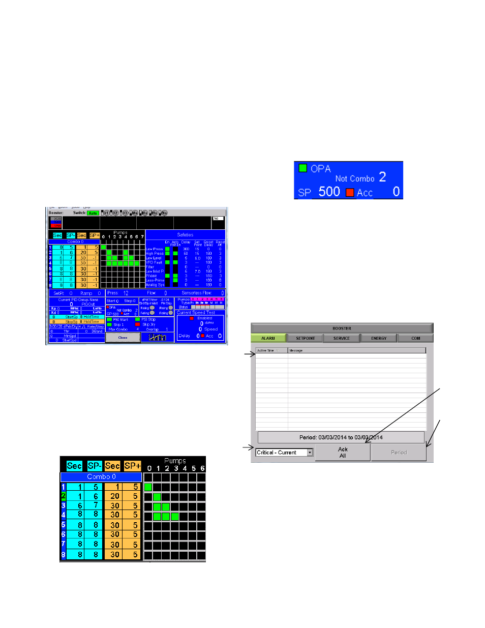
Figure 26: Combo Information
This field shows, from left to right, the current
combo (highlighted), start time, psi below
setpoint, stop time and psi above setpoint to
stop, for each combo. To the right is a table
detailing the pumps to run in each combo.
The example above shows combo 1 consists
of the PM Pump, Combo 2 consists of pump 1
(or any other single pump in the same group),
combo 3 is two main pumps, and combo 4 is 3
main pumps.
Figure 27: Combo Information
This shows the Overpressure accumulator settings.
“Not Combo” indicates that OPA will operate at any
combo level above 2.
ALARMS
The [ALARMS] tab will take you to the Alarms detail
screen.
Figure 2 8 : Alarms Home Screen
a. The Alarm history field will display particular alarms
based on the drop down selection detail in (b). The
time of the alarm and the type of alarm will be
displayed.
b. Drop down selection that will allow you to sort
alarms
i.
Critical – Current (current day)
ii.
Critical – History
iii.
Non-Critical
a
b
c
d