Bell & Gossett 10-001-275 XLS Integrated Pump Controller User Manual
Page 25
25
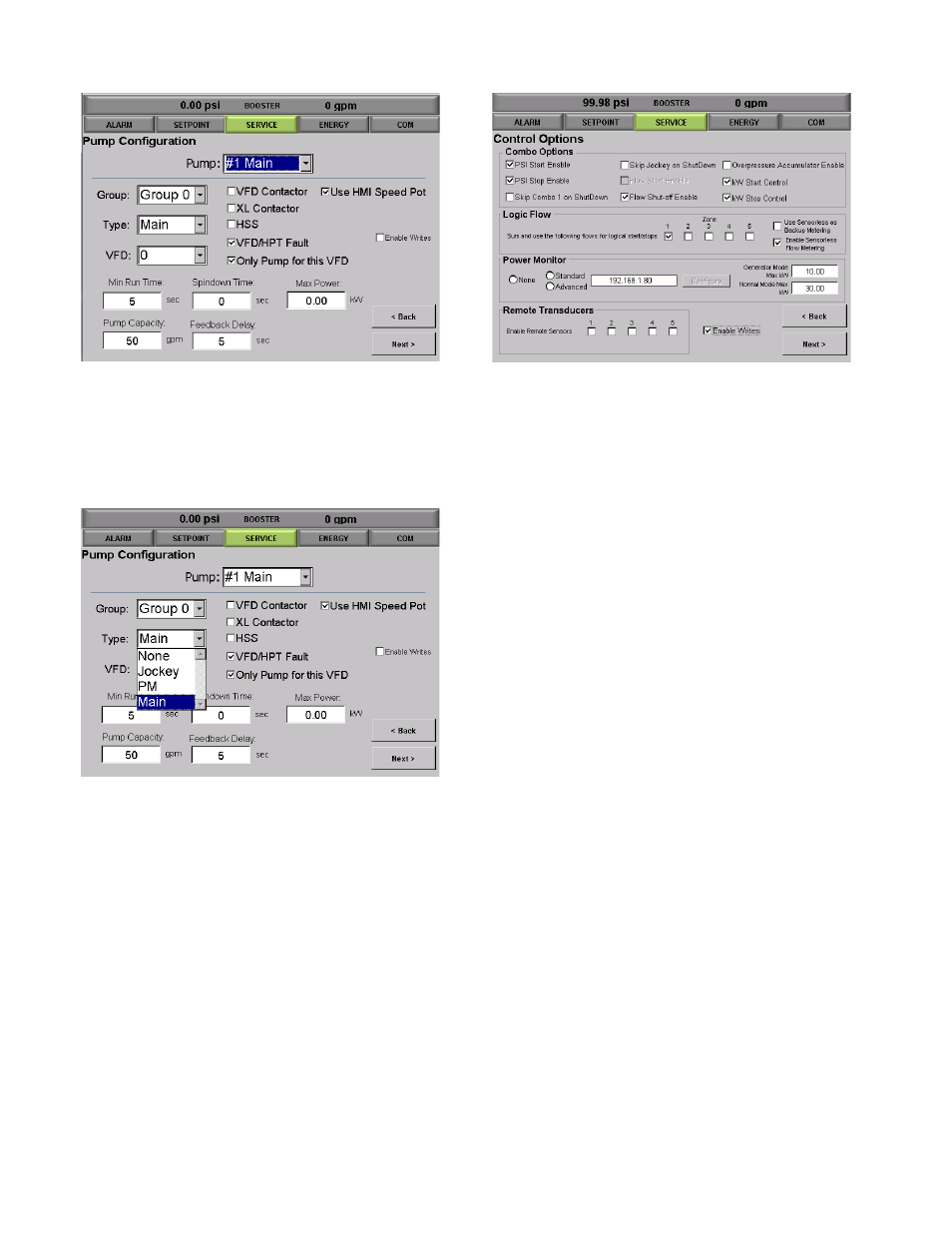
Figure 5 8 : Pump Configuration
Each pump can be selected from a drop down menu in
this screen. It can be assigned a group, type (Main,
Jockey, or PM), and number of VFDs that are going to
be used.
Figure 5 9 : Pump Type Configuration
Selections can be made regarding the pump being a
XL, VFD, HPT, HSS, or Only pump
for this VFD. For most Booster Stations these
selections will be limited to your configured set up.
Contact the factory for special configurations.
Enter the minimum run time, Spindown Time, Pump
Capacity, Feedback Delay for each pump.
Tap [Next] to move to the next System Setup
screen.
Control Options
This section will allow you to configure the control options
for the system.
Figure 60: Control Options
Combo Options
This section allows you to make various selections on
control options for the station detailed below.
“PSI Start Enable”
“PSI Stop Enable”
“Skip Combo 1 on ShutDown”
“Skip Jockey on ShutDown”
“Flow Shot-off Enable”
“Overpressure Accumulator Enable”
“kW Start Control”
“kW Stop Control”
Logic Flow
This section allows the user to enable the Dynamic Flow
Loss Compensation Mode. This mode will use built in
logic to determine the flow rate of the system and
calculate system losses without the need for external
mounted flow meters or pressure transmitters.
Power Monitor
This section allow the use to set up the use of an extrnal
power monitior.
“None, Standard or Advanced”
These are the options available for power
monitoring.
“Generator Mode Max kW”
This is the current allowable “Maximum Power”
set for the station in Generator Mode. Generator
Mode is a pre-configured factory option that
allows for the use of emergency power
generators in the event that main power is lost.