Bell & Gossett 10-001-275 XLS Integrated Pump Controller User Manual
Page 14
14
c. The [Ack All] button will clear any alarms that are
currently active.
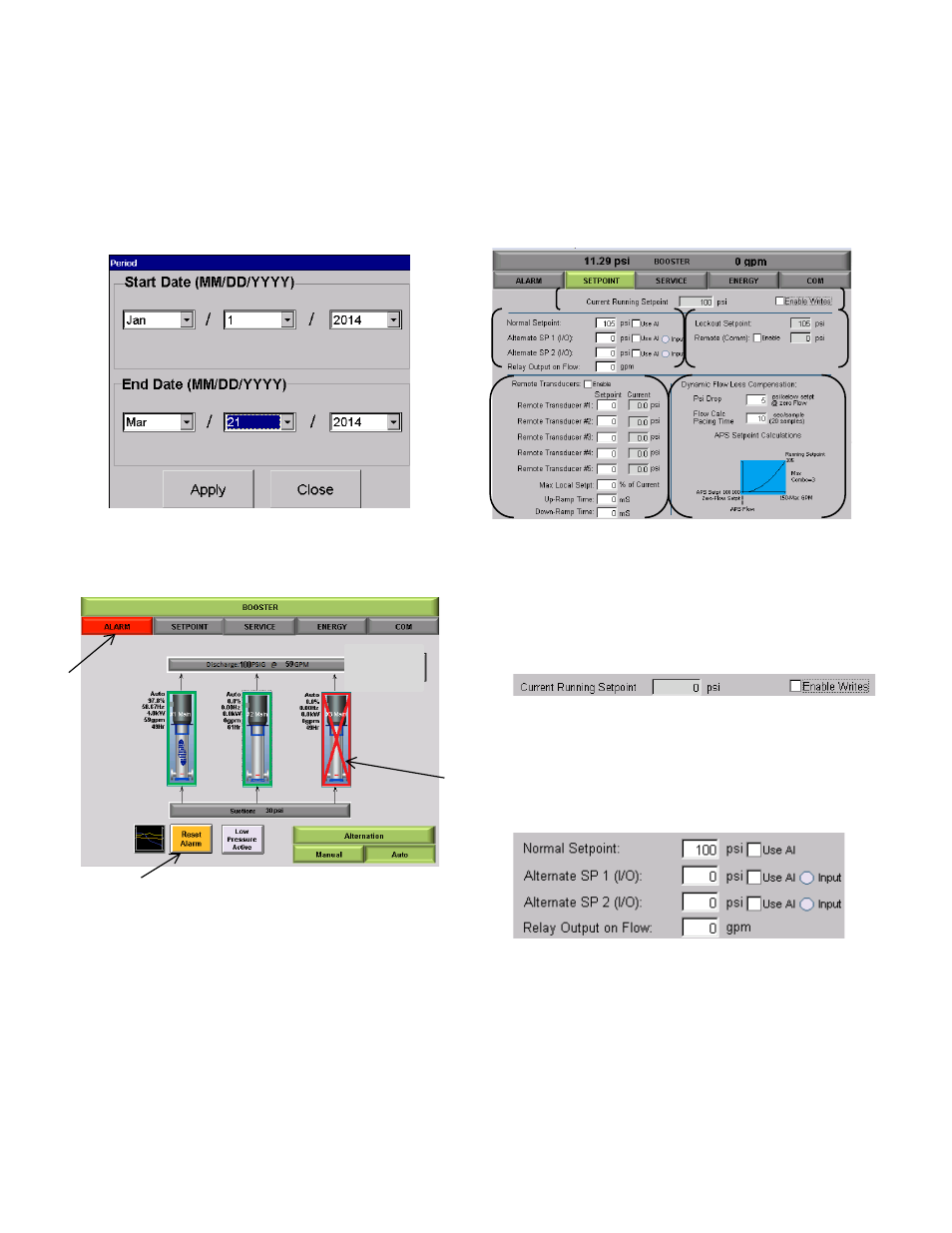
d. Tapping [Period], available in ‘Critical – History” and
“Non-Critical” modes, will open an enhanced screen
shown in Figure 29 to allow for the display of only
alarms during a given range.
Figure 29: Period Screen
If an alarm is active the Home screen will also display
various visual warnings to alert the system status
Figure 30: Alarm Warning
a. The [ALARM] will turn red to alert that there is an
active alarm.
b. [Reset Alarm] will flash from yellow to red to indicate
there is an active alarm. By tapping [Reset Alarm],
the alarm will be acknowledged.
c. The pump status will show an alarm state
SETPOINTS
The [SETPOINTS] tab will take you to the Setpoint detail
screen. From this screen you will be able to view the
station setpoints along with the current values of certain
parameters.
Figure 3 1 : Setpoint Home Screen
a. This portion of the screen displays the current
running set point of the station and the “enable
writes” check box. By checking this box any
changes made while in this screen will be saved.
By leaving it unchecked no changes can be
made.
Figure 3 2 : Setpoint Detail A
b. This portion of the screen will display the current
set points being used by the system. When
tapping in the numbered area an enhanced
keypad will appear that will allow you to change
the current value.
Figure 3 3 : Setpoint Detail B
If factory configured, checking the “Use AI”
check box will allow control by a factory
configured Analog Input. This input is separate
from the settings for remote transducers or BMS
override. If you do not have an external AI
configured, these boxes should remain
unchecked.
The “Input” indicator will be active if that current
input is on.
b
a
c
a
b
c
d
e