Allied Telesis OmniConnect ISDN User Manual
Page 14
OmniConnect / ISDN
User’s Manual
Page 8
Part number 613-10787-00
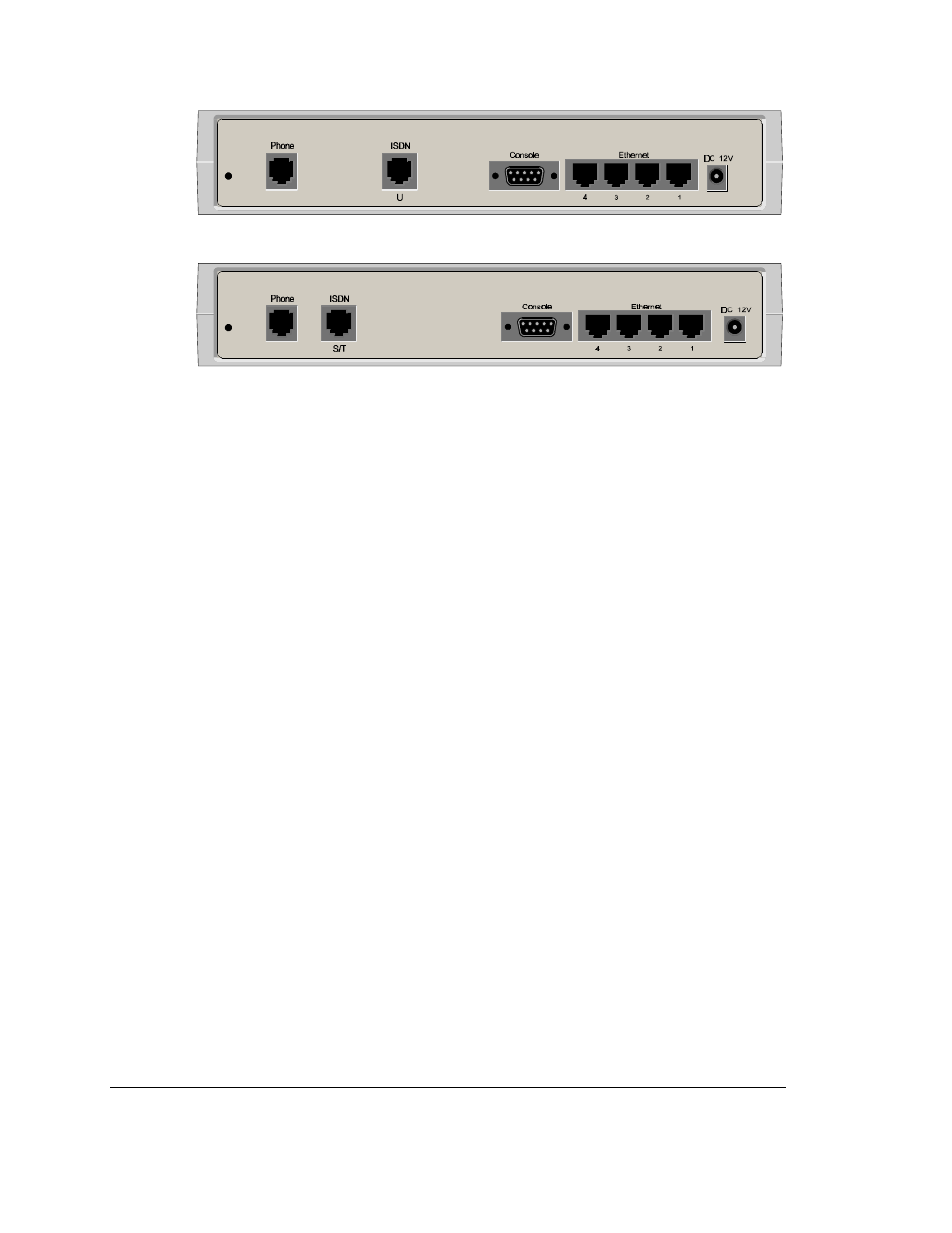
Figure 2-2
Rear Panel OmniConnect/ISDN (U) Remote Access Internet access device
Figure 2-3
Rear Panel OmniConnect/ISDN (ST) Remote Access Internet access device
The connectors and switches on the rear panel of the OmniConnect/ISDN (U) and
OmniConnect/ISDN (ST) allow connections to an external analog phone, ISDN U or ST
interface, serial console, 10Base-T network and DC power. The following provides a brief
description of each of the connectors and switches on both models.
2.4.7. Phone (analog POTS line)
POTS connection to an external telephone, facsimile machine or answering machine. This is a
standard phone jack (RJ-11 style connector).
2.4.8. ST (ISDN S/T)
ISDN line from an external NT1 (RJ-45 connector). This connector is only present on the
OmniConnect/ISDN (ST) model.
2.4.9. U (ISDN U)
ISDN line from telephone company (RJ-45 connector). This connector is only present on the
OmniConnect/ISDN (U) model.
2.4.10. Console (serial console)
Nine pin (DB-9 female) connector to an external RS-232C compatible terminal or computer.
2.4.11. Ethernet (four 10Base-T)
Four Unshielded Twisted Pair (UTP) 10Base-T Ethernet LAN ports (RJ-45 connector). Port 1
is used for connections to other repeaters and PCs. Ports 2-4 are used solely for connections to
PCs. In order to connect the OmniConnect/ISDN access devices to another hub, the MDI
switch at the bottom of the access device must be moved to the ON position. The
OmniConnect/ISDN devices are shipped with the switch in the OFF position, for connection
to PCs. When attempting to move the switch position, please use a non-conductive (plastic)
object.
2.4.12. Power (DC 12V)
DC 12V power supply connection to the OmniConnect/ISDN. This input takes a 12V, 1A
regulated supply.