Cabling a media converter stack, Chapter 2: installation 52 – Allied Telesis AT-MCF2000M User Manual
Page 52
Chapter 2: Installation
52
Cabling a Media Converter Stack
To create a stack, connect the units together in a daisy
chain topology using the Stack ports on the AT-MCF2000M
and AT-MCF2000S modules. The Stack port on the
AT-MCF2000M Management Module must be connected to
the Stack 1 or Stack 2 port on the AT-MCF2000S Stacking
Module in the next chassis of the stack. The remaining
Stack port on the stacking module must be connected to
either the Stack 1 or Stack 2 port in the next chassis, and so
on. Loops are not supported. For cable specifications, refer
to “Cable Requirements” on page 42.
Note
Allied Telesis recommends reviewing the information
in “Guidelines to Building a Stack” on page 27 before
cabling the stack.
To cable a stack, perform the following procedure:
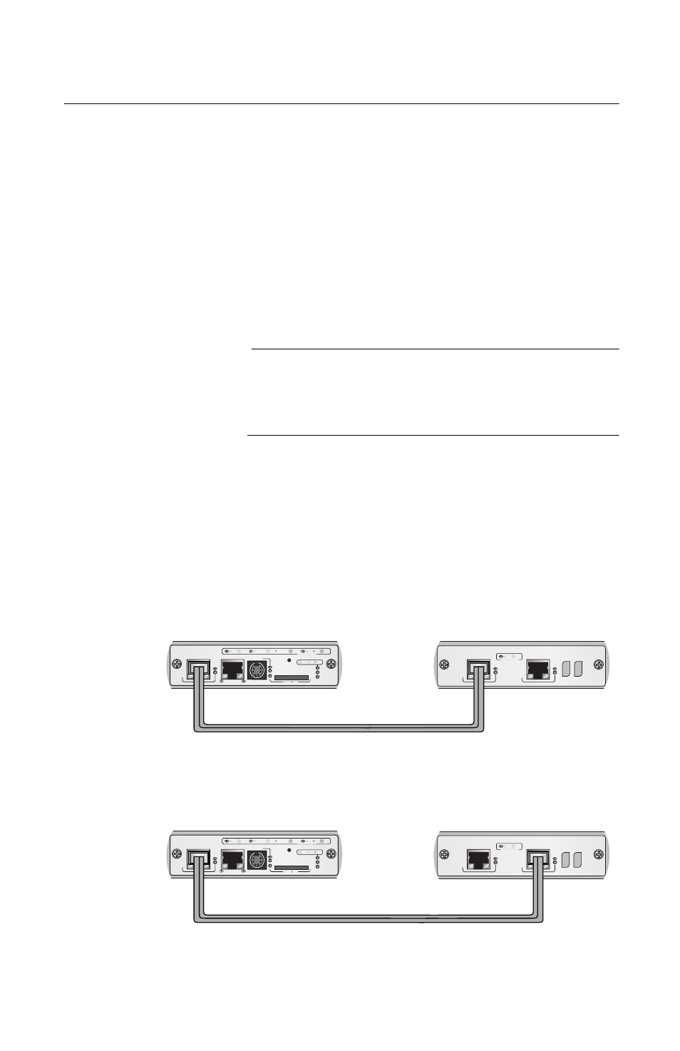
1.
To connect a management module to a stacking
module, connect the management module’s Stack port
to either the Stack 1 or Stack 2 port on the stacking
module, as illustrated in Figure 18.
Figure 18. Cabling the AT-MCF2000M Management
Module to the AT-MCF2000S Stacking Module
AT-MCF2000S
LINK
ACT
PORT ACTIVITY
STACK 1
STACK 2
AT-MCF2000M
STACK
MANAGEMENT
TERMINAL
10/100/1000BASE-T
RS-232
RESET
SD
RDY
BUSY
MASTER
POWER
BOOT
RDY
FAULT
1000 LINK
ACT
10/100 LINK
ACT
FDX
HDX
COL
LINK
ACT
PORT ACTIVITY
AT-MCF2000S
LINK
ACT
PORT ACTIVITY
STACK 1
STACK 2
AT-MCF2000M
STACK
MANAGEMENT
TERMINAL
10/100/1000BASE-T
RS-232
RESET
SD
RDY
BUSY
MASTER
POWER
BOOT
RDY
FAULT
1000 LINK
ACT
10/100 LINK
ACT
FDX
HDX
COL
LINK
ACT
PORT ACTIVITY
CHASSIS ID
CHASSIS ID
OR
AT-MCF2000M Management
Module
AT-MCF2000S Stacking
Module