Figure 15: installing the management module – Allied Telesis AT-MCF2000M User Manual
Page 49
AT-MCF2000M Management Module Installation Guide
49
3.
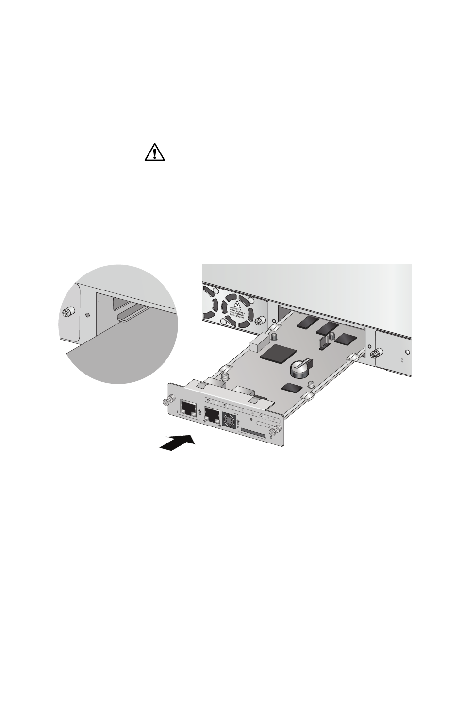
Align the edges of the module with the guides in the
slot and carefully slide the module into the chassis until
it is flush with the front of the chassis. Refer to Figure
15. Light pressure may be necessary to firmly seat the
module connector on the connector on the back panel
of the chassis.
Caution
Do not force the module into place. Doing so may
damage the connector pins on the backplane of the
chassis. If there is resistance, remove the module and
reinsert it after verifying that the edges of the card are
properly aligned in the guides in the chassis’ module
slot.
Figure 15. Installing the Management Module
AT-MCF2KF
AN
NORMA
L
FAULT
STATU
S
AT-MCF2000M
STACK
MANAGEM
ENT
TERMINAL
10/100/1000
BASE-T
RS-232
RESET
SD
RDY
BUSY
MASTER
POWER
BOOT
RDY
FAULT
1000 LINK
ACT
10/100 LIN
K
ACT
FDX
HDX
COL
LINK
ACT
PORT ACTIVITY
1200a
- AT-GS908M (54 pages)
- AT-x230-10GP (80 pages)
- AT-GS950/48PS (64 pages)
- AT-GS950/10PS (386 pages)
- AT-GS950/16PS (386 pages)
- AT-GS950/48PS (386 pages)
- AT-9000 Series (258 pages)
- AT-9000 Series (1480 pages)
- IE200 Series (70 pages)
- AT-GS950/48 (60 pages)
- AT-GS950/48 (410 pages)
- AT-GS950/8 (52 pages)
- AT-GS950/48 (378 pages)
- SwitchBlade x8106 (322 pages)
- SwitchBlade x8112 (322 pages)
- SwitchBlade x8106 (240 pages)
- SwitchBlade x8112 (240 pages)
- AT-TQ Series (172 pages)
- AlliedWare Plus Operating System Version 5.4.4C (x310-26FT,x310-26FP,x310-50FT,x310-50FP) (2220 pages)
- FS970M Series (106 pages)
- 8100L Series (116 pages)
- 8100S Series (140 pages)
- x310 Series (116 pages)
- x310 Series (120 pages)
- AT-GS950/24 (404 pages)
- AT-GS950/24 (366 pages)
- AT-GS950/16 (44 pages)
- AT-GS950/16 (404 pages)
- AT-GS950/16 (364 pages)
- AT-GS950/8 (364 pages)
- AT-GS950/8 (52 pages)
- AT-GS950/8 (404 pages)
- AT-8100 Series (330 pages)
- AT-8100 Series (1962 pages)
- AT-FS970M Series (330 pages)
- AT-FS970M Series (1938 pages)
- SwitchBlade x3112 (294 pages)
- SwitchBlade x3106 (288 pages)
- SwitchBlade x3106 (260 pages)
- SwitchBlade x3112 (222 pages)
- AT-S95 CLI (AT-8000GS Series) (397 pages)
- AT-S94 CLI (AT-8000S Series) (402 pages)
- AT-IMC1000T/SFP (23 pages)
- AT-IMC1000TP/SFP (24 pages)
- AT-SBx3106WMB (44 pages)