Front panel, Chapter 1: overview 20, At-mcf2000m – Allied Telesis AT-MCF2000M User Manual
Page 20
Chapter 1: Overview
20
Front Panel
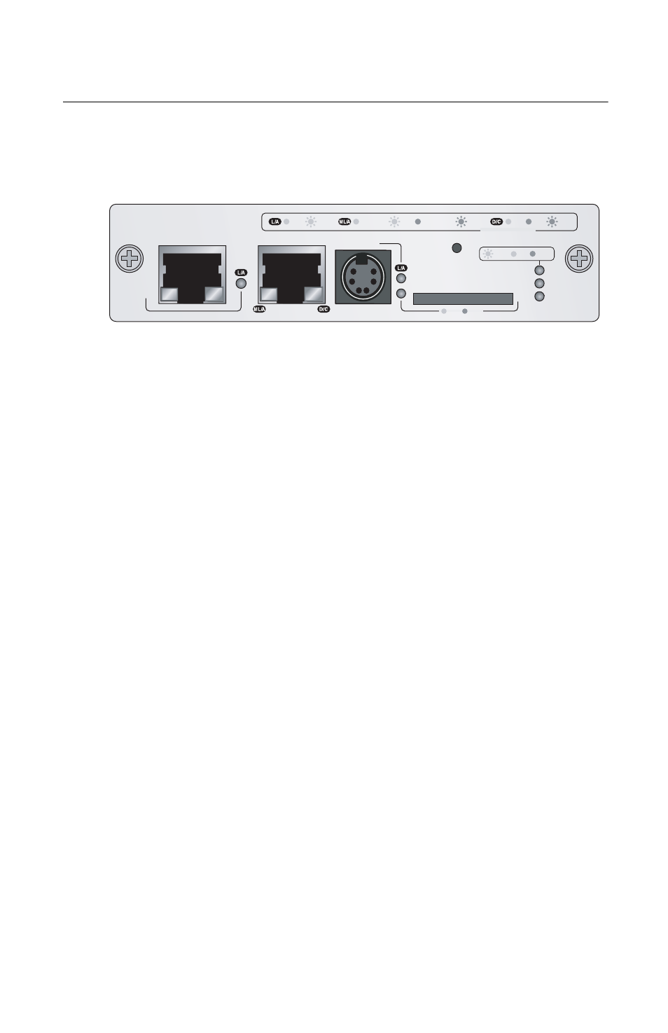
Figure 2 illustrates the front panel of the AT-MCF2000M
Management Module.
Figure 2. Front Panel of the AT-MCF2000M Management
Module
The components of the panel are mentioned here:
Stack port - Multiple media converter devices can be
managed as a single unit through this port. For further
information, refer to “Stack Port” on page 24.
10/100/1000Base-T Management Port - This standard
Ethernet, Fast Ethernet, and Gigabit Ethernet port adds
support for management functions that require access
to a network, such as remote (in-band) management
from a Telnet or Secure Shell (SSH) client and
downloading or uploading files to a TFTP server. For
further information, refer to “10/100/1000Base-T
Management Port” on page 21.
RS-232 Terminal port - Local (out-of-band) management
of the chassis or stack is performed through this port
with a console or a PC with a terminal emulation
program. For further information, refer to “RS-232
Terminal Port” on page 23.
Reset button - This button performs a soft reset of the
module by initializing the AT-S97 Management
Software. For further information, refer to “Reset Button”
on page 29.
SD slot - This slot can accommodate a secure digital
memory card for storing configuration files or
transferring files between management modules. For
further information, refer to “SD Slot” on page 31.
AT-MCF2000M
STACK
MANAGEMENT
TERMINAL
10/100/1000BASE-T
RS-232
RESET
SD
RDY
BUSY
MASTER
POWER
BOOT
RDY
FAULT
1000 LINK
ACT
10/100 LINK
ACT
FDX
HDX
COL
LINK
ACT
PORT ACTIVITY
1199