Chapter 2: installation 50, 1201a, 1202a – Allied Telesis AT-MCF2000M User Manual
Page 50: At-mcf2kf an
Chapter 2: Installation
50
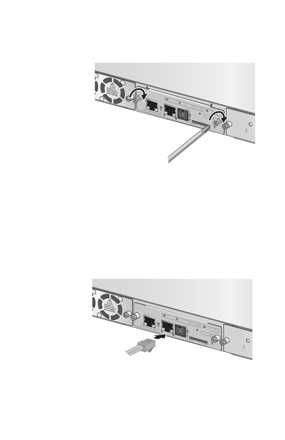
4.
Secure the management module to the chassis by
tightening the two captive screws on the module with a
cross-head screwdriver. Refer to Figure 16.
Figure 16. Securing the Management Module
5.
Connect a standard TIA/EIA 568-B-compliant
Enhanced Category 5 (Cat 5e) shielded or unshielded
cable to the 10/100/1000Base-T Management port.
Refer to Figure 17. Connect the other end of the cable
to a network device, such as a Fast Ethernet or Gigabit
Ethernet switch.
You can skip this step if the management module will
not require access to your network. For background
information, refer to “10/100/1000Base-T Management
Port” on page 21.
Figure 17. Connecting an Enhanced Category 5 Network
Cable to the 10/100/1000Base-T Management Port
1201a
AT-MCF
2000
M
STACK
MANAG
EMENT
TER
MINAL
10/100/1000
BASE-T
RS-232
RES
ET
SD
RDY
BUSY
MAS
TER
POWER
BOOT
RDY
FAULT
1000 L
INK
ACT
10/100
LINK
ACT
FDX
HDX
COL
LINK
ACT
PORT A
CTIVITY
AT-MCF2KF
AN
NORM
AL
FAULT
STATUS
1202a
AT-MCF
2000
M
STACK
MANAG
EMENT
TER
MINAL
10/100
/1000
BASE-T
RS-232
RES
ET
SD
RDY
BUSY
MASTER
POWER
BOOT
RDY
FAULT
1000 L
INK
ACT
10/100
LINK
ACT
FDX
HDX
COL
LINK
ACT
PORT A
CTIVITY
AT-MCF2KF
AN
NORM
AL
FAULT
STATUS