Electrical pressure, Calibration reference check – Ashcroft ATE-100 Handheld LCD Digital Calibrator User Manual
Page 63
- 63 -
Revision 4.6 3/2004
accompanied the product shipment from the factory.
See section 27.0 “Access Code” for information on lost
passwords.
Step 8
With the correct access code displayed press the
enter key.
ENT
The calibrator will respond by displaying:
Electrical
Pressure
The electrical calibration process allows for the cali-
bration of the current and voltage input measurement
capability of the base unit and calibration of the 0/1 vdc
analog component of the interface between the base unit
and the Quick Select module in use.
Step 9
When this screen appears, the word “Electrical”
for electrical recertification is already flashing. There-
fore, press the enter key to commence the electrical
calibration.
ENT
The calibrator will respond by displaying:
Calibration
Reference Check
Step 10
To perform “as received” readings use the down
arrow key to select Reference Check. When selected the
text “Reference Check” will flash on the display.
Calibration
Reference Check
Step 11
With text Reference Check Flashing press the
Enter Key.
ENT
The calibrator will respond by displaying:
———
1.0V
-.xxxxx RefCheck
*****WARnInG*****
If the voltage standard is set to a level in excess of the
recommended calibration input or is connected to incor-
rect pins or in contact with pins adjacent to the specified
input pins during the calibration process the base unit
electronics may be damaged. Use extreme caution when
connecting test leads and applying test voltage inputs.
The Model CQS Calibration Quick Select module is
available to simplify connection of the voltage stan-
dard to the base unit. The module provides banana jack
connections for the input of the voltage standard to the
calibrator base unit.
Step 12
To check the measured voltage using a preci-
sion voltage source apply 1.00000 volt
±
50 microvolts.
Do not use a voltage less than or greater than 1 volt
±
50 microvolts.
When the calibrator is ready to mea-
sure the reference voltage it will display:
Apply 1.00000V
to J3 pin 7
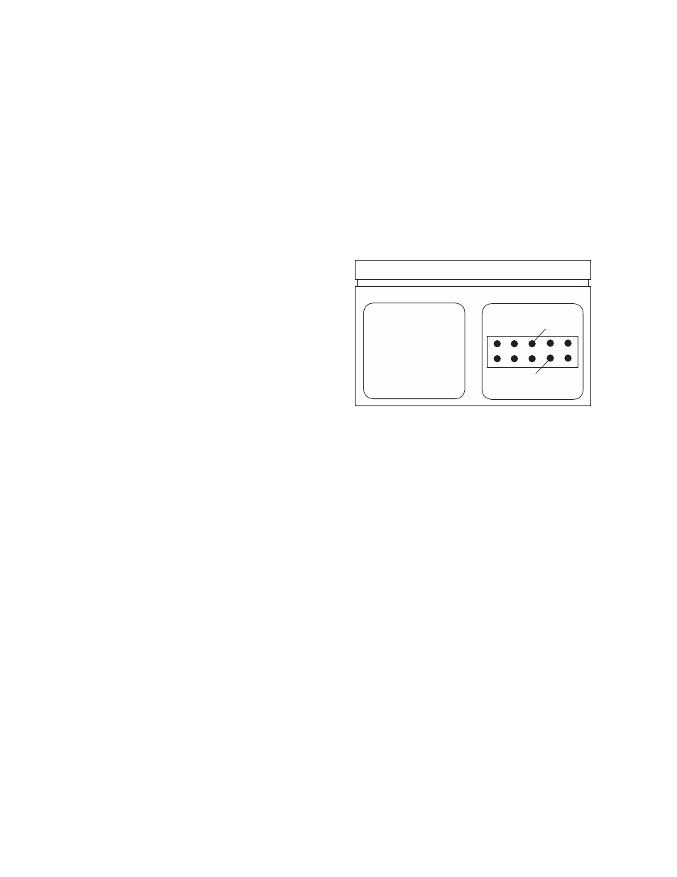
These pins are located in the connector in module bay
#1 as shown below.
To apply the 1 Vdc signal to the calibrator connect the
precision voltage generator so that the positive line is
connected to Pin 7 and the ground is connected to Pin 6.
Step 13
The value displayed under the dashed line rep-
resents the as received reading for the 1 Vdc measure-
ment. The reading will look as follows:
——–––—
1.0V
+.99998 RefCheck
(Reading must be between 0.99995 and 1.00005 for base
unit to be within specification.)
After taking note of the reading press the enter key to
proceed to the next as received reading. The calibrator
will respond by displaying the following:
——–––—
0.1V
-.xxxxx RefCheck
This is used for calibration of the 20mA measurement
capability. The measured value must be within 0.03%
of the applied voltage for the current measurement to be
within the 0.03% of full scale specification.
Step 14
To check the measured voltage using a preci-
sion voltage source:
Apply 0.100000V
to J3 pin 7
Pin 7
Pin 6