Calib rtmodule – Ashcroft ATE-100 Handheld LCD Digital Calibrator User Manual
Page 62
- 62-
Revision 4.6 3/2004
Section 27.0
Recertification of the Calibrator
Both the base unit and the pressure modules can be
recalibrated and recertified in the field. The base unit
includes a firmware based, menu driven procedure that
provides operator prompts to facilitate the recalibration
process. The procedure encompasses both the acquisi-
tion of “as found” data and performing adjustment and
recalibration of the base unit and modules. The recertifi-
cation program is accessed via the set up menu key.
Access Code
The calibration data is password protected with an
access code. The recalibration access code is different
than the owner access code. Both of the access codes
are provided with the calibrator at time of shipment and
are located on the base unit calibration certificate. If
the access code has been lost contact the factory and be
prepared to provide the serial number of the base unit.
The serial number is located on the product label in the
module bay of the base unit. To locate the product label
remove any installed pressure modules, hold the base
unit keypad side down and look into the module bays.
The label is located on the underside of the keypad/front
panel section of the base unit.
Section 27.1
Calibration/Recertification Overview
The base unit calibration firmware provides a means
of linearization and recertification of pressure modules
and the base unit’s electrical input (Vdc/mA) calibration
reference. In addition, the base unit employs a preci-
sion 1 VDC reference for interfacing with the modules
which can be calibrated. The calibration of this reference
is critical to ensure the combined output of pressure
module and base unit is within rated accuracy.
Section 27.2 Required Equipment
The following equipment is required to perform recali-
bration or recertification of the calibrator.
1. A precision voltage supply capable of providing
1 Vdc
±
50 microvolts (±0.00005 Vdc)
2. Primary pressure standard with an accuracy rating of
4:1 compared to the rating of the pressure module to
be tested.
3. Test leads with banana jacks and mini clips.
4. Recommended – Model CQS calibration quick
select module. Although recalibration and recertifica-
tion work can be performed with out it, this module
will greatly simplify the process and reduce risk of
damage to the base unit.
Section 27.3
As Received Readings of the
Base Unit Electronics
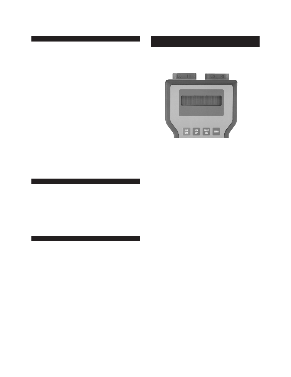
Please note. The following convention is used when
referring to modules or module bays in this procedure.
Step 1
Remove any installed measurement modules.
If the CQS calibration module is to be used, install it in
module bay #1 at this time.
Step 2
Turn power on and allow for at least 15 minutes
warm up time.
Step 3
With the calibrator powered up and displaying a
dashed line across the display, press the set up key.
SET
UP
Step 4
Using the arrow keys locate the text “Calib” in
the set up menu.
Calib RTmodule
Using the arrow keys select the text “Calib” from the
set up menu. When the calibration function has been
selected it will flash on the display.
Step 5
With the text “Calib” displayed and flashing
press the enter key.
ENT
Step 6
The calibrator will respond by displaying:
Access code ?
.00000
Step 7
Enter the 5 digit calibration access code pro-
vided with the base unit.
Access code ?
12345
Note:
The access code is specific for the base unit being
used. The code is provided on the certification sheet that
Module Bay #1
Module Bay #2